Page 19 www.NabcoEntrances.com 5-7-10
Nabco Multi-Module
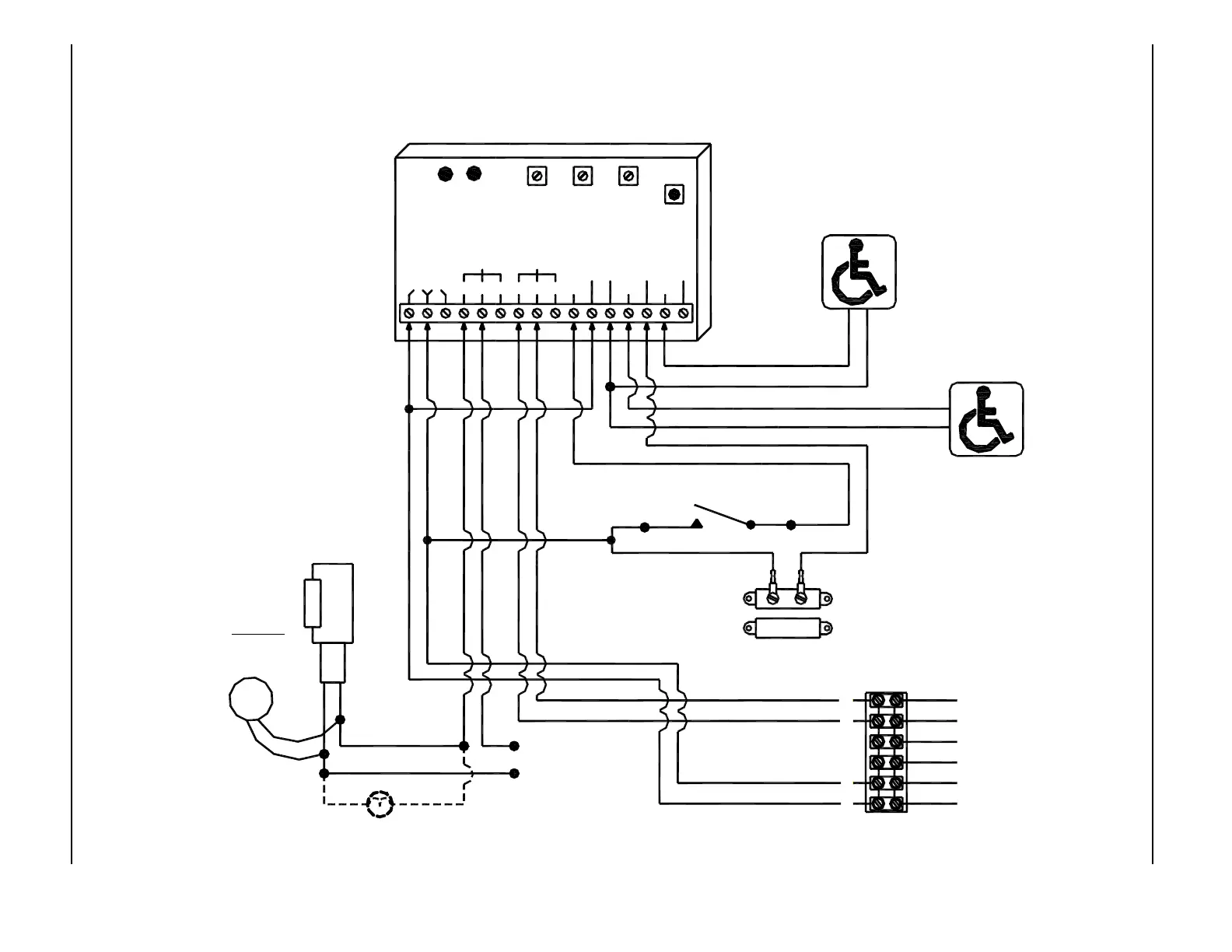
MODE 6 - WASHROOM CONTROL RELAY DIAGRAM - MAGNUM 4 CONTROL
NOTES:
1. Fail Safe Strike Used
2. A black circle indicates a
wire connection.
3. Power supply inputs not
polarity sensitive.
iti-200S
RELAY2RELAY1
WET3WET2
DRY2DRY1
DRY
COMCOM
WET
WET1N.O. COM N.C.N.C.COMN.O.
12V24V
LED LED
RL2RL1
RELAY 1
ON TIME
DOO
(DELAY
ON
OPERATE)
RELAY 2
RELAY 2
ON TIME
SW 1
MODE
SWITCH
DN 0302
Terminal Strip on Magnum Control
BROWN
BLACK
RED
WHITE
VIOLET
ORANGE
1
2
3
4
5
6
Interior Push Plate
Normally Open - Dry Contacts
Exterior Push Plate
Normally Open - Dry Contacts
Magnetic Door Position Switch
P/N 14-11313
Contacts close when door is closed
Connect to COM and N.O. terminals on switch.
Push to Lock Switch
ELECTRIC
STRIKE
TVS
Optional Occupied Light
Fail Safe
Connect Transient
(supplied)
directly to strike.
Voltage Suppressor
Not polarity sensitive.
STRIKE POWER
(To match strike
voltage)