Page 8 www.NabcoEntrances.com 5-7-10
Nabco Multi-Module
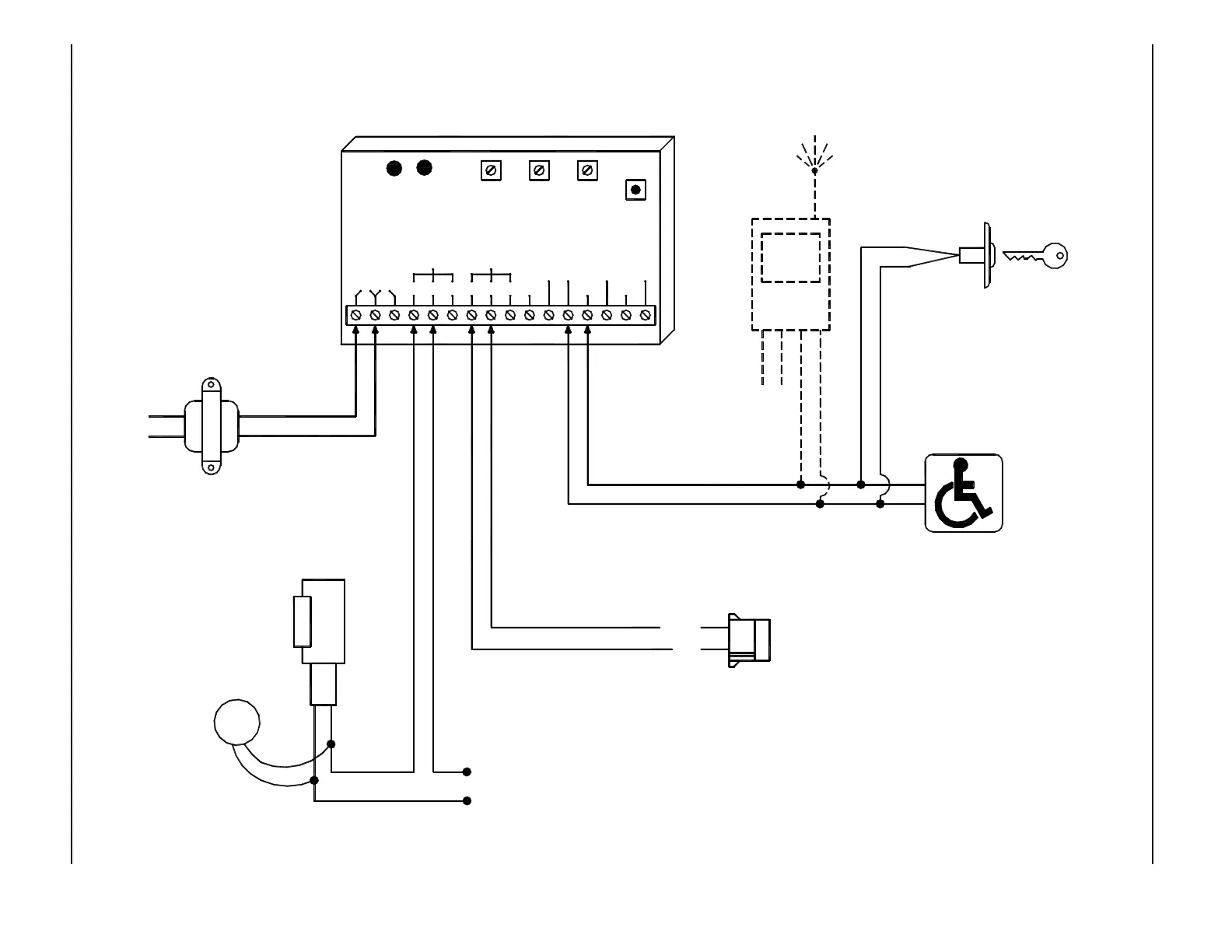
MODE 1 - ELECTRIC STRIKE SEQUENCER DIAGRAM - ANALOG CONTROL
Normally Open - Dry Contacts
EXTERIOR KEY SWITCH
INTERIOR PUSH SWITCH
Normally Open - Dry Contacts
Transformer
P/N 14-2101
24 VAC
24 VAC120 VAC
(IF USED)
Power
STRIKE POWER
(To match strike
voltage)
Note:
1. A black circle indicates
a wire connection.
2. Power supply inputs not
polarity sensitive.
If magnetic
lock or fail safe
strike used,
connect lock
wires to COM
and N.C.
terminals of
Multi-Module
iti-200S
TVS
ELECTRIC
STRIKE
N.O.
COM
Power
4-TERM
RECEIVER
RADIO
RELAY2RELAY1
WET3WET2
DRY2DRY1
DRY
COMCOM
WET
WET1N.O. COM N.C.N.C.COMN.O.
12V24V
LED LED
RL2RL1
RED
BLACK
Activation Connector on Analog Control
RELAY 1
ON TIME
DOO
(DELAY
ON
OPERATE)
RELAY 2
RELAY 2
ON TIME
SW 1
MODE
SWITCH
DN 0302
Connect Transient
(supplied)
directly to strike.
Voltage Suppressor
Not polarity sensitive.