Page 18 www.NabcoEntrances.com 5-7-10
Nabco Multi-Module
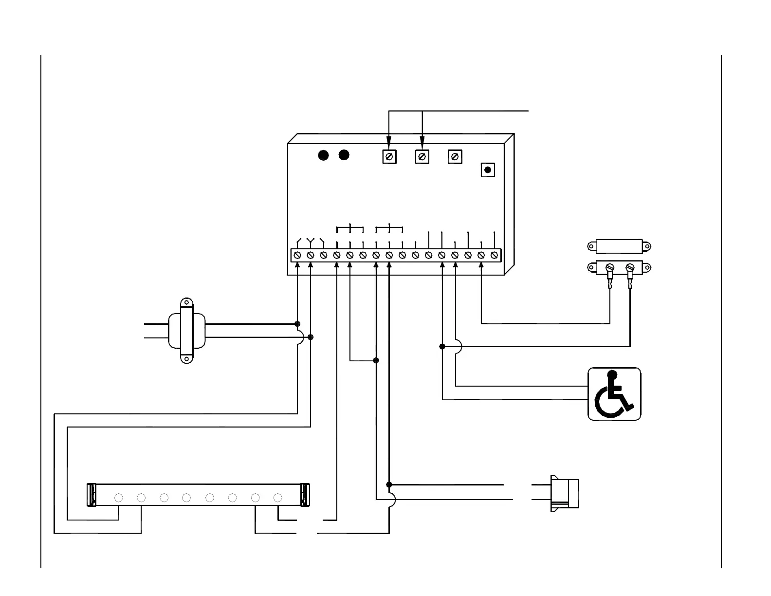
MODE 5 - ACUGARD LOCK OUT RELAY DIAGRAM - ANALOG CONTROL
NOTES:
1. Sensor only active after push
plate is actuated. It will stay
active until the door shuts and
door position switch closes.
Multi-Module will reset after 2
minutes if the door does not
open for any reason.
2. A black circle indicates a
wire connection.
3. Power supply inputs not
polarity sensitive.
Activation Push Plate
Normally Open - Dry Contacts
Transformer
P/N 14-2101
24 VAC
120 VAC 24 VAC
These Potentiometers have no effect
Acugard 3 LE on Non-swing side of door
P/N 21-10158-35
1 2 3 4 5 6 7 8
COM
N.O
Magnetic Door Position Switch
P/N 14-11313
Contacts should close when door is
closed - Connect to COM and N.O.
terminals on switch.
iti-200S
RELAY2RELAY1
WET3WET2
DRY2DRY1
DRY
COMCOM
WET
WET1N.O. COM N.C.N.C.COMN.O.
12V24V
LED LED
RL2RL1
RELAY 1
ON TIME
DOO
(DELAY
ON
OPERATE)
RELAY 2
RELAY 2
ON TIME
SW 1
MODE
SWITCH
DN 0302
RED
BLACK
Activation Connector on Analog Control