Page 15 www.NabcoEntrances.com 5-7-10
Nabco Multi-Module
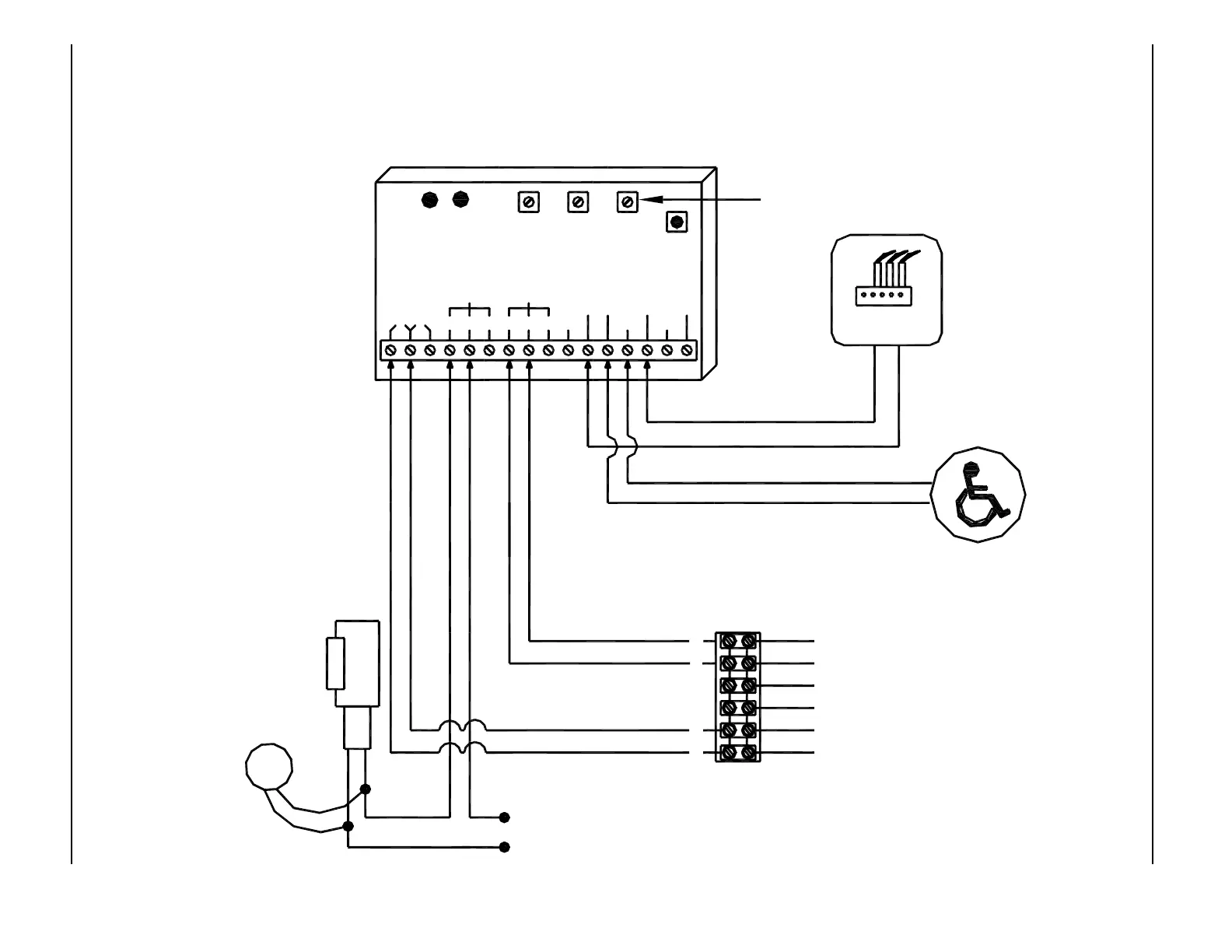
MODE 4 - SMOKE EVACUATION DIAGRAM - MAGNUM 4 CONTROL
FIRE
12-24V AC/DC
Fire Alarm Panel
Shown with maintained
and powered signal (WET)
BROWN
BLACK
RED
WHITE
VIOLET
ORANGE
1
2
3
4
5
6
If magnetic
lock or fail safe
strike used,
connect lock
wires to COM
and N.C.
terminals of
Multi-Module
ELECTRIC
STRIKE
strike voltage)
(To match
TVS
STRIKE POWER
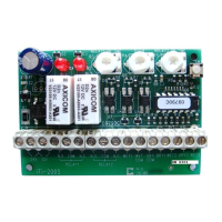
iti-200S
RELAY2RELAY1
WET3WET2
DRY2DRY1
DRY
COMCOM
WET
WET1N.O. COM N.C.N.C.COMN.O.
12V24V
LED LED
RL2RL1
RELAY 1
ON TIME
DOO
(DELAY
ON
OPERATE)
RELAY 2
RELAY 2
ON TIME
SW 1
MODE
SWITCH
DN 0302
NOTES:
1. In smoke evacuation or
maintained operator mode the
module can be triggered by a
wet input or a dry contact like a
sensor or any other relay
contact.
2. A black circle indicates a
wire connection.
3. Common and N.O. on
Acusensor 1B are Yellow wires.
4. Power supply inputs not
polarity sensitive.
This potentiometer has no effect
Terminal Strip on
Magnum Control
Not polarity sensitive.
Voltage Suppressor
directly to strike.
(supplied)
Connect Transient
PUSH SWITCH
Normally Open - Dry Contacts