Page 9 www.NabcoEntrances.com 5-7-10
Nabco Multi-Module
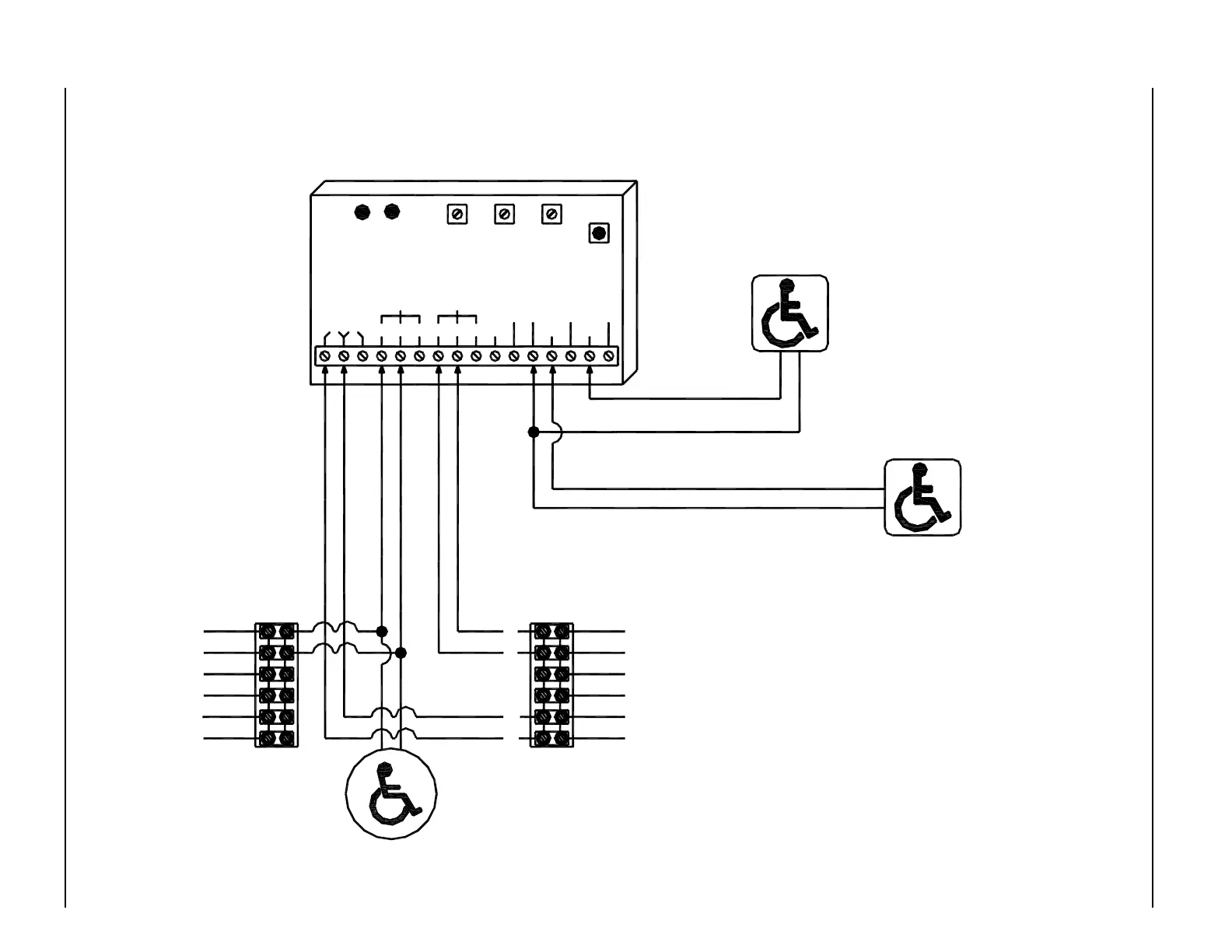
MODE 1 - BI-DIRECTIONAL DOOR SEQUENCER DIAGRAM - MAGNUM 4 CONTROL
NOTE:
1. When the module is triggered
by push switch (DRY1)
Relay # 1 will activate
first, then after an adjustable
delay, Relay # 2 will activate.
When the module is triggered
by the push switch (DRY2)
Relay # 2 will activate
first, then after an adjustable
delay, Relay # 1 will activate.
2. A black circle indicates a
wire connection.
3. Power supply inputs not
polarity sensitive.
Normally Open - Dry Contacts
OPTIONAL VESTIBULE PUSH SWITCH
BROWN
BLACK
RED
WHITE
VIOLET
ORANGE
Normally Open - Dry Contacts
EXTERIOR PUSH SWITCH
INTERIOR PUSH SWITCH
Normally Open - Dry Contacts
6
5
4
3
2
1
ORANGE
VIOLET
WHITE
RED
BLACK
BROWN
DN 0302
SW 1
MODE
SWITCH
RELAY 2
ON TIME
DOO
(DELAY
ON
OPERATE)
RELAY 2
RELAY 1
ON TIME
RL1 RL2
LEDLED
24V 12V
N.O. COM N.C. N.C.COMN.O. WET1
WET
COM COM
DRY
DRY1 DRY2
WET2 WET3
RELAY1 RELAY2
iti-200S
Terminal Strip on
Interior Magnum
Control
Terminal Strip on
Exterior Magnum
Control