Page 16 www.NabcoEntrances.com 5-7-10
Nabco Multi-Module
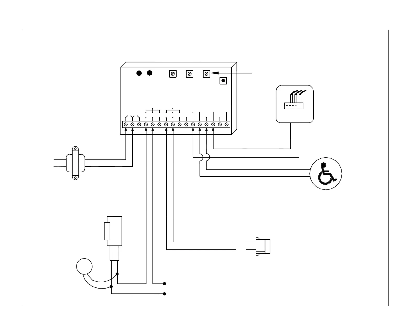
MODE 4 - SMOKE EVACUATION DIAGRAM - ANALOG CONTROL
SW 1
MODE
SWITCH
RELAY 2
ON TIME
DOO
(DELAY
ON
OPERATE)
RELAY 2
RELAY 1
ON TIME
RL1 RL2
LEDLED
24V 12V
N.O. COM N.C. N.C.COMN.O. WET1
WET
COM COM
DRY
DRY1 DRY2
WET2 WET3
RELAY1 RELAY2
iti-200S
STRIKE POWER
TVS
STRIKE
ELECTRIC
If magnetic
lock or fail safe
strike used,
connect lock
wires to COM
and N.C.
terminals of
Multi-Module
and powered signal (WET)
Shown with maintained
Fire Alarm Panel
12-24V AC/DC
FIRE
(To match
strike voltage)
DN 0302
Activation Connector on Analog Control
BLACK
RED
Normally Open - Dry Contacts
PUSH SWITCH
Connect Transient
(supplied)
directly to strike.
Voltage Suppressor
Not polarity sensitive.
120 VAC 24 VAC
Transformer
P/N 14-2101
24 VAC
This potentiometer has no effect
NOTES:
1. In smoke evacuation or
maintained operator mode the
module can be triggered by a
wet input or a dry contact like a
sensor or any other relay
contact.
2. A black circle indicates a
wire connection.
3. Common and N.O. on
Acusensor 1B are Yellow wires.
4. Power supply inputs not
polarity sensitive.