Rev. 3-12-13 Part #15-9000-30
www.NabcoEntrances.com U30 Microprocessor Control
3-7 Input and Output Features
CHAPTER 3: INPUT AND OUTPUT FEATURES
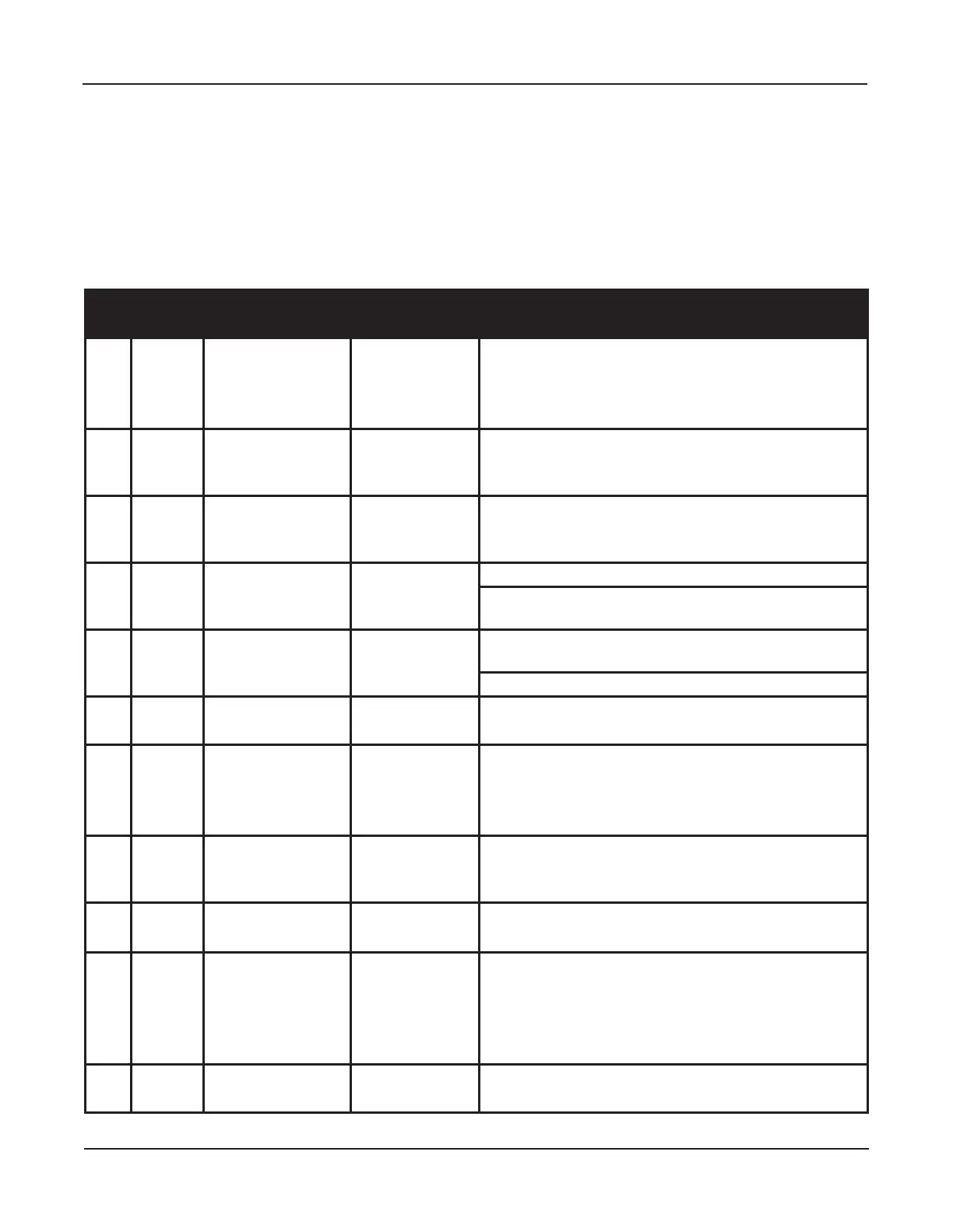
16 Pin Terminal Block Assignments (All wires are idened by color)
No. Symbol Funcon Wire Color* Descripon
1 9DC 12V 12 VDC+ Brown Output Terminal:
● Sensor power source Output Terminal
● Output is 12 VDC with a maximum capacity of 0.35 amps
(350 mA).
2 7 Common Red Output Terminal:
Provides common ground for the 12 VDC power and signal
source.
3 61 Interior Acviaon Black Acvaon Signal Input:
Opens the door based on a signal from the Sensor that is
acve in one way mode.
4 6B Holding Beam White Holding Beam Input:
Opens or re-opens a door when the holding beam signal is
acvated.
5 H Reduced Opening
Switch
Green Reduced Opening Input:
Enables reduced door opening when switched to Red (7)
6 M0
One Way
Mode Switch Orange Input for Switch 1 (SW1):
Used to achieve special funcons.
7 M1 Night Mode Switch * Orange/ White Input for Switch 2 (SW2):
● Used to achieve special funcons.
● All references to Mode Switches are made in connecon
with ground (Red).
8 62 Exterior Acvaon * Black/ Red Input Terminal:
Receives signal from a Sensor that is switched out in ONE
WAY mode.
9 SQ Sequenal Acvaon Yellow Input Terminal:
Allows a sequence of signals to open and close the door.
10 BA Breakout Detector Blue Input Terminal:
● Connects directly to Red (7) during normal operaon.
● When the Rocker Switch is turned OFF or if the door is
panicked open, it is disconnected from Red (7) causing Slide
door to stop operang.
11 SLS Misellaneous Input * Green/ White Input Terminal:
Receives signal from Sidelite Sensor or addional devices.