EasyManua.ls Logo

NAD 512 Service Manual

NAD 512
28 pages
To Next Page IconTo Next Page
Page #1 background imageLoading...
Page #1 background image
SERVICE
SAFETY
PRECAUTIONS
(UL)
1.
Use
exact
replacement
parts
for
critical
locations
marked
/J\
7
2.
Return
lead
dress
to
original
position
and
re-install
protective
covers.
3.
Before
returning
to
customer,
test
for
shock
hazard;
use
either
mothod
A
or
B:
ICE
MANU,
A.
Leakage
test
“cold”:
1.
Unplug
the
AC
cord;
turn
power
switch
ON.
2.
Connect
one
lead
of
High
Voltage
Insulation
Tester
to
both
prongs
of
the
AC
plug.
3.
Touch
other
lead
to
all
exposed
metal
parts.
4,
Impedance
measurement
must
be
0.3-5.0
Megohms.
B.
Leakage
test,
“live”
:
1.
Plug
unit
directly
into
the
AC
outlet:
do
not
use
isolation
transformer.
2.
Connect
one
lead
of
the
Leakage
Current
Tester
to
earth
ground.
3.
Touch
other
lead
to
all
exposed
metal
parts.
COMPACT
DISC
PLAYER
SER
on
or—
|
Lo
ou
a
o
=o
O02
(Oa)

Other manuals for NAD 512

Question and Answer IconNeed help?

Do you have a question about the NAD 512 and is the answer not in the manual?

NAD 512 Specifications

General IconGeneral
BrandNAD
Model512
CategoryCD Player
LanguageEnglish

Summary

Service Safety Precautions

Leakage Test Procedures

Outlines methods for performing cold and live leakage tests for safety compliance.

Safety Information

Laser Radiation Warnings

Provides safety warnings and precautions related to invisible laser radiation.

Specifications

Controls and Physical Specifications

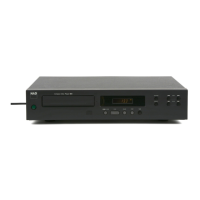
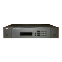
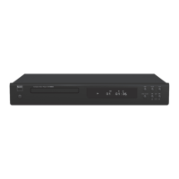
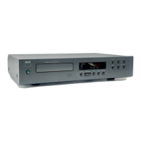
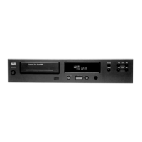
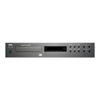
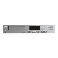
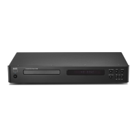
Details the player's controls and its physical dimensions.

Panel Overview

Rear and Front Panel Identification

Identifies all connectors and controls located on the rear and front panels.

Block Diagram

Wiring Diagram

Disassembly Instructions

Top Cover Removal

Step-by-step instructions for removing the unit's top cover.

Alignment Procedure

Adjustment Points Diagram

Diagram showing critical adjustment points on the main PCB.

PLL Adjustment

Procedure for calibrating the Phase Locked Loop (PLL) circuit.

RF Adjustment

Procedure for adjusting the Radio Frequency (RF) signal output.

EF Balance Adjustment

Procedure for balancing the Error والف (EF) signal.

Focus Gain Adjustment

Procedure for adjusting the focus gain parameter.

Tracking Gain Adjustment

Procedure for adjusting the tracking gain parameter.

Focus and Tracking Gain Adjustment Guidance

Gain Adjustment Troubleshooting

Table of symptoms and corresponding focus/tracking gain adjustments.

Important Notes

Optical System Pick-Up Handling

Precautions for handling the optical system pick-up to prevent damage.

Laser Beam Emission Safety

Safety guidelines for checking laser beam emission and objective lens movement.

Laser Pick-Up Replacement Precautions

Static Discharge Prevention for Pick-up

Methods to prevent electrostatic discharge damage during pick-up replacement.

PCB Layout (Parts Side)

IC Block Diagrams

Q101 and Q103 IC Diagrams

Internal block diagrams for ICs CXA1081M and CXD1167Q.

Q102 and Q105 IC Diagrams

Internal block diagrams for ICs CXA1082BQ and MN6471M/MN6474M.

Troubleshooting Guide

Exploded View

Exploded View Parts List

Mechanism Exploded View

Mechanism Service Parts List

Electrical Parts List

Capacitors

Detailed list of capacitors with part numbers and specifications.

Mechanism Parts List Continuation

Mechanism Component Details

Continuation of mechanism parts list with additional components.

Resistors and Variable Components

Switches, Jacks, and Miscellaneous

Lists switches, RCA jacks, and miscellaneous items.

Packing Diagram

Related product manuals