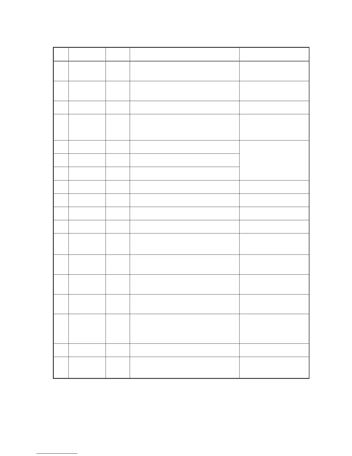
2-21
Pin
No.
Pin name I/O Description Remark
57 DOUT
O
3I/F
Digital-out output pin. Digital data for up to
double speed can be output when a
frequency of 16.9344 MHz is used.
As per CP-1201
58 AOUT
O
3I/F
Audio data output pin. Which bit is first
(MSB first or LSB first) can be selected,
using a command.
—
59 BCK
O
3I/F
Bit clock output pin. 32fs, 48fs, and 64fs
can be selected, using a command.
Normal speed
: 32fs = 1.4112 MHz
60 LRCK
O
3I/F
LR channel clock output pin. "L" for the
L-channel and "H" for the R-channel. The
output polarity can be inverted, using a
command.
Normal speed: 44.1 kHz
61 AIN
I
3I/F
1-bit DAC external input: AIN
62 BCKI
I
3I/F
1-bit DAC external input: BCKI
63 LRCKI
I
3I/F
1-bit DAC external input: LRCKI
1-bit DAC external input
64 VDD1 —
1.5 V supply voltage pin dedicated to the
DSP circuit.
65 VSS1 —
1.5 V grounding pin dedicated to the DSP
circuit.
66 AWRC
O
3AI/F
VCO control pin for active wide range. Controllable in CLV/CAV.
67 PVDD3 —
3.3 V supply voltage pin dedicated to the
PLL circuit.
—
68 PDO
O
3AI/F
Pin for outputting a phase difference signal
between the EFM signal and PLCK signal.
Quaternary output
(PVDD3, HiZ, VSS, and
PV
REF
).
69 TMAX
O
3AI/F
Pin for outputting the result of TMAX
detection.
The TMAX pin output the same signal.
Ternary output
(PVDD3, VSS, and Hiz).
70 LPFN
I
3AI/F
Pin for receiving an inverted output of the
PLL-circuit low-pass filter amp.
The resistance side is
connected. See an
applicable circuit diagram.
71 LPFO
O
3AI/F
Pin for the PLL-circuit low-pass filter amp
output.
The capacitor side is
connected. See an
applicable circuit diagram.
72 PVREF —
1.65 V reference supply voltage pin
dedicated to the PLL circuit.
Connected to the V
REF
and PV
REF
within the IC.
A 0.1 uF capacitor is
connected.
73 VCOF
O
3AI/F
VCO filter pin. —
74 VCOREF
I
3AI/F
Input pin for the VCO center frequency
reference level.
To be connected to the
PV
REF
if the AWRC is not
used.