FP0 RTD Unit
I/O Allocation and Sample Programs
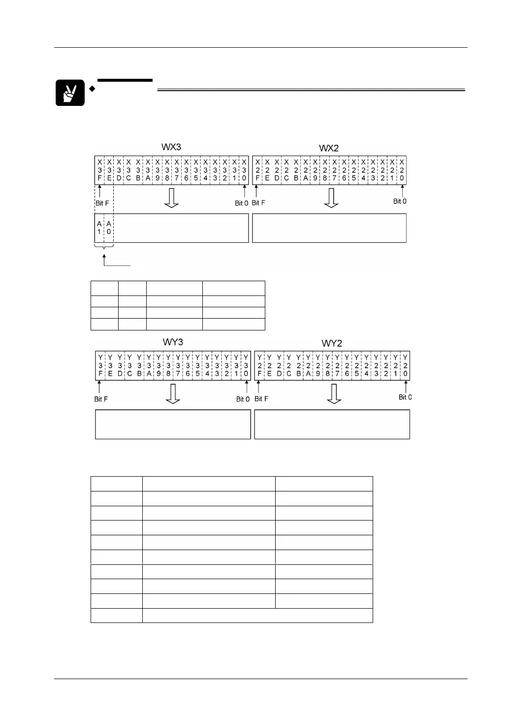
EXAMPLE
The converted digital data is assigned to WX2 and WX3 when the FP0 RTD unit
is installed as expansion unit no. 1.
Conversion data switch flag
Converted data for CH1, 3, and 5
(signed 14-bit data)
Converted data for CH0, 2, and 4
(signed 16-bit data)
A1 A0 WX3 WX2
0 0 CH1 data CH0 data
0 1 CH3 data CH2 data
1 0 CH5 data CH4 data
Unused
For assignment, see table below
Assignment of outputs Y20…Y27
.
Off On
Y20
°C °F
Y21
CH0: 0.1°C/°F CH0: 0.01°C/°F
Y22
CH1: 0.1°C/°F CH1: 0.01°C/°F
Y23
CH2: 0.1°C/°F CH2: 0.01°C/°F
Y24
CH3: 0.1°C/°F CH3: 0.01°C/°F
Y25
CH4: 0.1°C/°F CH4: 0.01°C/°F
Y26
CH5: 0.1°C/°F CH5: 0.01°C/°F
Y27
Always off Always off
Y28…Y2F
Unused
15
 Loading...


