When an Error Occurs
FP0 RTD Unit
6 When an Error Occurs
6.1 Troubleshooting
PROCEDURE
1. Check whether the input signal lines are connected properly.
When the RTD is not connected properly or broken, K8191 is displayed for RTD
types Pt100, Pt1000, and Ni1000. K16383 is displayed for the RTD type Resistor.
2. Check whether the input range setting switch is set properly.
It specifies the allowed temperature range and the RTD type.
3. Use the programs described above.
REFERENCE
For further information, see page 4, Input Range Setting Switch and page 14, I/O
Allocation and Sample Programs.
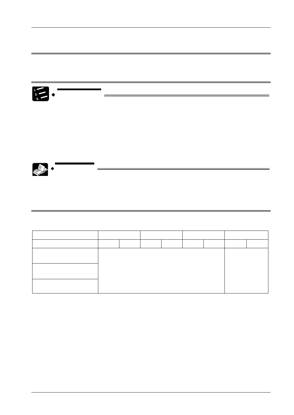
6.2 Digital Value When Out Of Measuring Range
When the input of the FP0 RTD unit is out of the measuring range, the following digital values
are displayed:
Pt100 [°C/°F] Pt1000 [°C/°F] Ni1000 [°C/°F]
Resistor [Ω]
Resolution [K/°F] 0.1 0.01 0.1 0.01 0.1 0.01 1 0.1
Temperature measured
> upper-limit
Temperature measured
< lower-limit
RTD connected
improperly or broken
8191 16383
20

 Loading...

