FP0 RTD Unit
I/O Allocation and Sample Programs
Conversion data switch flag
When transferring the data from the FP0 RTD unit to the control unit, it is converted to 32-bit
data including the channel information. Data for WX2 can be used as is, but the following
procedure is required for WX3 data since its higher 2 bits are used as a conversion data
switch flag.
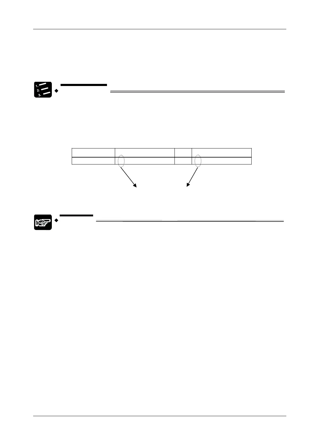
PROCEDURE
1. As resistor data is only positive, handle the complete data of bit 0 to bit F
for WX2 and bit 0 to bit D for WX3 as the resistance value.
2. The higher 2 bits for WX3 are used as conversion data switch flag. After
saving the channel information, the conversion data switch flag needs to be
masked. Mask the data using “00” as the conversion data is positive.
Data for CH3 WX3
→
Data after masking
1 0100000000000001 → 0000000000000001
Conversion data switch flag
NOTE
X3E, X3F, WX2 and WX3 may be different, depending on where the FP0 RTD
unit is installed.
19
 Loading...


