I/O Allocation and Sample Programs
FP0 RTD Unit
5 I/O Allocation and Sample Programs
5.1 I/O Numbers
Up to three expansion units including the FP0 RTD unit can be connected to the CPU (2
words [2x16 bits] are assigned to each WX and WY).
I/O Numbers
FP0/FPΣ CPU
Expansion unit
1 2 3
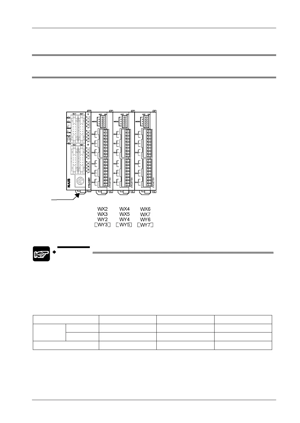
WY3, WY5, and WY7 are allocated but not used.
NOTES
• Always install the FP0 RTD unit the farthest to the right of the control unit.
• With 3 expansion units, one of which being the FP0 RTD unit, mount the
FP0 RTD unit in the place of expansion unit no. 3.
• With 3 expansion units, two of which being FP0 RTD units, mount the FP0
RTD units in the places of expansion units no. 2 and no. 3.
With the setup illustrated above, the I/O data is allocated as in the table below.
Expansion Unit No.1 Expansion Unit No.2 Expansion Unit No.3
CH0, 2, 4
WX2 WX4 WX6
RTD input
channel
CH1, 3, 5
WX3 WX5 WX7
RTD output
WY2 WY4 WY6
14

 Loading...

