W415-1285 / A / 11.03.14
17
EN
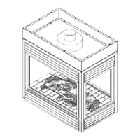
3.9 VERTICAL TERMINATION
(H
T
) < (V
T
)
Simple venting configurations.
See graph to determine the required vertical rise V
T
for the
required horizontal run H
T
.
REQUIRED
VERTICAL
RISE IN FEET
(METERS) V
T
HORIZONTAL VENT RUN PLUS OFFSET IN FEET (METERS) H
T
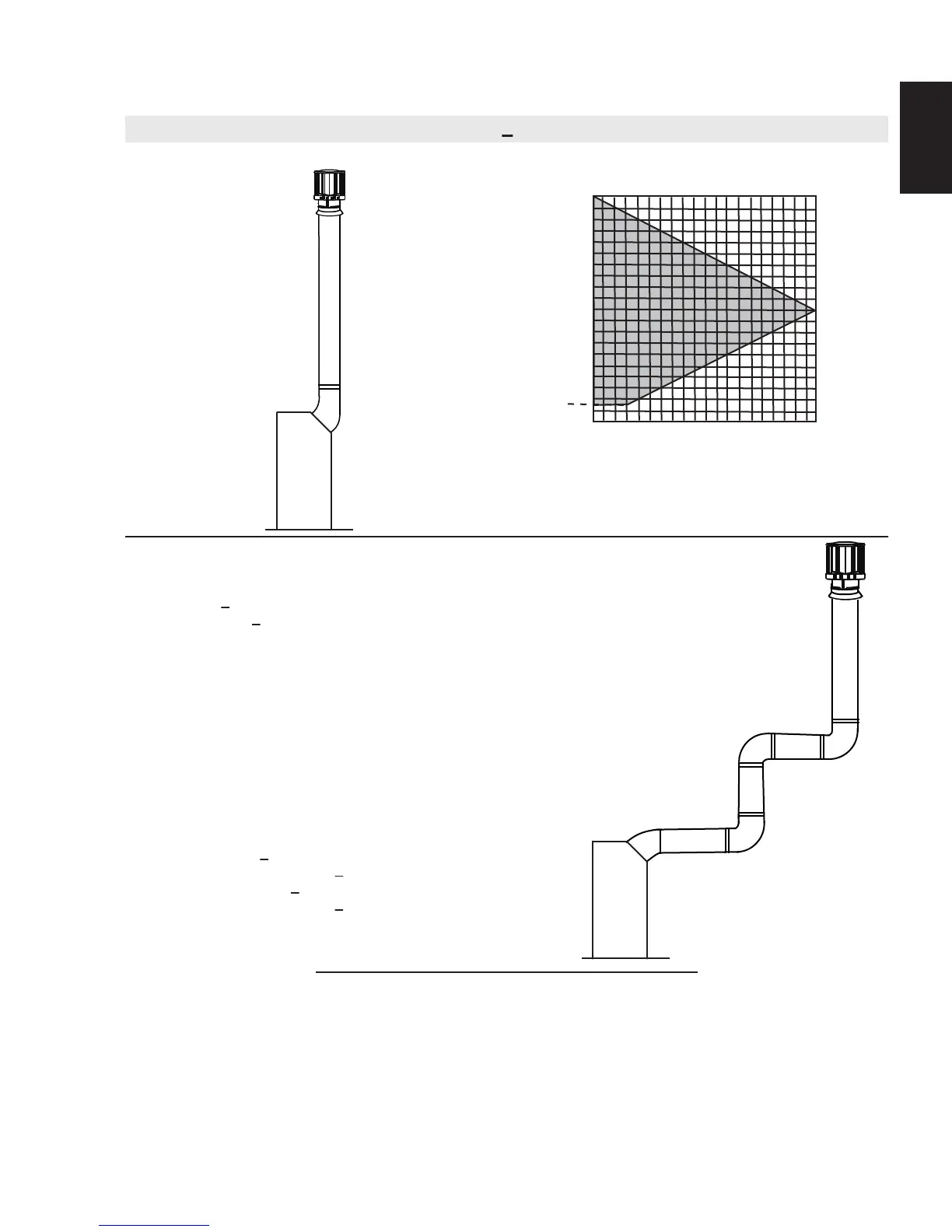
For vent configurations requiring more than one 45° and one 90° elbow, the following formulas apply:
Formula 1: H
T
< V
T
Formula 2: H
T
+ V
T
< 40 feet (12.2m)
Example:
V
1
= 5 FT (1.5m)
V
2
= 10 FT (3.1m)
V
T
= V
1
+ V
2
= 5 FT (1.5m) + 10 FT (3.1m) = 15 FT (4.6m)
H
1
= 3 FT (0.9m)
H
2
= 2.5 FT (0.8m)
H
R
= H
1
+ H
2
= 3FT (0.9m) + 2.5FT (0.8m) = 5.5 FT (1.7m)
H
O
= .03 (one 45° + three 90° elbows - 135°)
= .03 (45 + 270 - 135°) = 5.4 FT (1.6m)
H
T
= H
R
+ H
O
= 5.5 FT (1.7m)+ 5.4 FT (1.m) = 10.9 FT (3.3m)
H
T
+ V
T
= 10.9 FT (3.3m)+ 15 FT (4.6m) = 25.9 FT (7.9m)
Formula 1: H
T
< V
T
10.9FT (3.3m) < 15 (4.6m)
Formula 2: H
T
+ V
T
< 40 FT (12.2m)
25.9FT (7.9m) < 40 (12.2m)
Since both formulas are met, this vent configuration is acceptable.
The shaded area within the lines represents acceptable
values for H
T
and V
T
0
5
(1.5)
10
(3.1)
15
(4.6)
20
(6.1)
40 (12.2)
10 (3.1)
20 (6.1)
30 (9.1)
3 (0.9)
18.3A
90°
V
1
H
1
H
2
90°
90°
45°
V
2
 Loading...