41
IOM
W415-2288 / 08.29.2019
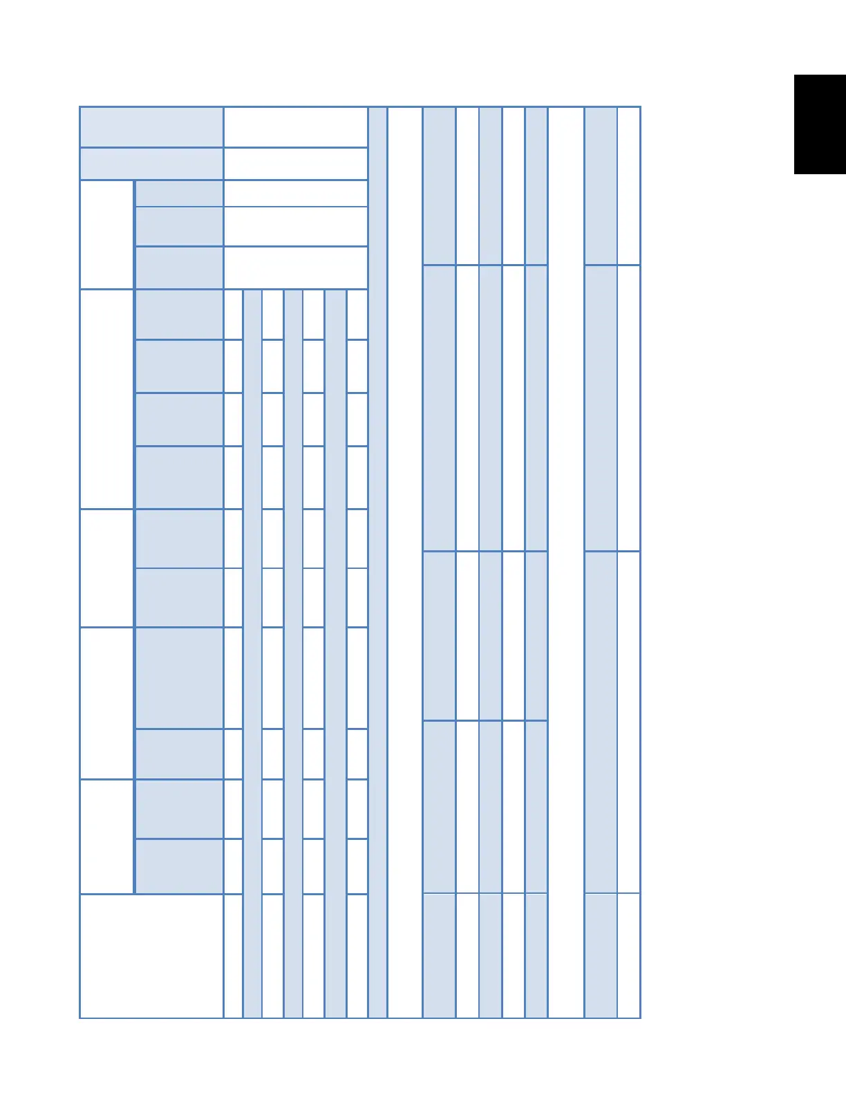
5.2.4 Electrical and Physical Data
TABLE 4.
Place top blower plate back into place..
Lift and place blower down into cabinet.
Connect Molex connector to the
front blower plate.
Install 10 screws to the front blower plate and
electrical plate (with capacitor and contactor on it).
Install electrical plate (with
capacitor and contactor attached).
Secure top blower plate using 10 round head
screws and 6 hex head screws.
Install seven screws along the back.
Check the insulation strip for damages.
Install heating module back.
Refer to steps 1-16 from ”Heating
Module Removal” section.
Electrical plate
50 51
52
5655
53
54
* Models with A18A & A24A Air Conditioning have two speed condenser fan motor.
Speed 1 is for A18A and Speed 2 is for A24A units.
Model No.
Min. Circuit
Ampacity
Protection
Compressor Outside Fan* Indoor Blower
Voltage/Hz/Phase
Voltage/Range
208V 240V 208V 240V
Comp
Rated
Load
Amps
(RLA)
Comp
Locked
Rotor
Amps
(LRA)
Dia
Nominal RPM
Rated Load
Amps
Cond
Mtr.
HP
Wheel Dia
Rated Load
10 x 6
2.8
208-230/60/1
197-253
Electric heating module components
Model
Circuit Breaker 1 Circuit Breaker 2 Temperature Cut-out- Auto Reset Fusible Link
135°F (57°C) open, 95°F (35°C) close
135°F (57°C) open, 95°F (35°C) close
135°F (57°C) open, 95°F (35°C) close
135°F (57°C) open, 95°F (35°C) close
Compressor and condenser fan branch circuit fuse size
Model Compressor RLA (A) Condenser Motor FLA (A) Fuse Size (A)