Chapter 3 I/O Information
© National Instruments Corporation 3-3 NI 8352/8353 User Manual
Universal Serial Bus
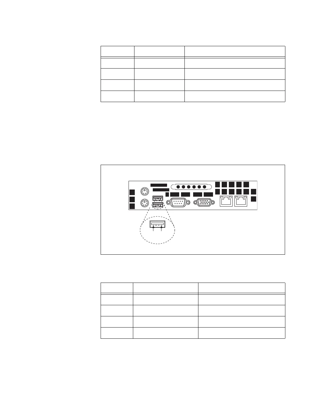
Figure 3-3 shows the location and pinouts for the Universal Serial Bus
(USB) connectors on the NI 8352/8353. Table 3-3 lists and describes the
USB connector signals.
AMP manufactures a USB mating connector, part number 787633.
Figure 3-3. USB Connector Location and Pinout
3 GND Ground
4 VCC VCC
5 CLK Clock Keyboard
6 NC Clock Mouse
Table 3-3. USB Connector Signals
Pin Signal Name Signal Description
1 VCC Cable Power (+5 V)
2 –Data USB Data–
3 +Data USB Data+
4 GND Ground
Table 3-2. PS/2 Connector Signals (Continued)
Pin Signal Name Signal Description
USB
4
1
 Loading...


