Chapter 3 I/O Information
NI 8352/8353 User Manual 3-4 ni.com
Serial
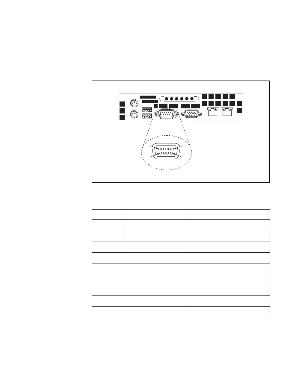
Figure 3-4 shows the location and pinouts for the serial connector on the
NI 8352/8353. Table 3-4 lists and describes the serial connector signal.
AMP manufactures a serial port mating connector, part number 745491-5.
Figure 3-4. Serial Connector Location and Pinout
Table 3-4. Serial Connector Signals
Pin Signal Name Signal Description
1 DCD* Data Carrier Detect
2 SIN* Receive Data
3 SOUT* Transmit Data
4 DTR* Data Terminal Ready
5 GND Ground
6 DSR* Data Set Ready
7 RTS* Ready to Send
8 CTS* Clear to Send
9 RI* Ring Indicator
1
5
9
6
Serial
 Loading...


