Chapter 7 Digital Routing
© National Instruments Corporation 7-3 E Series User Manual
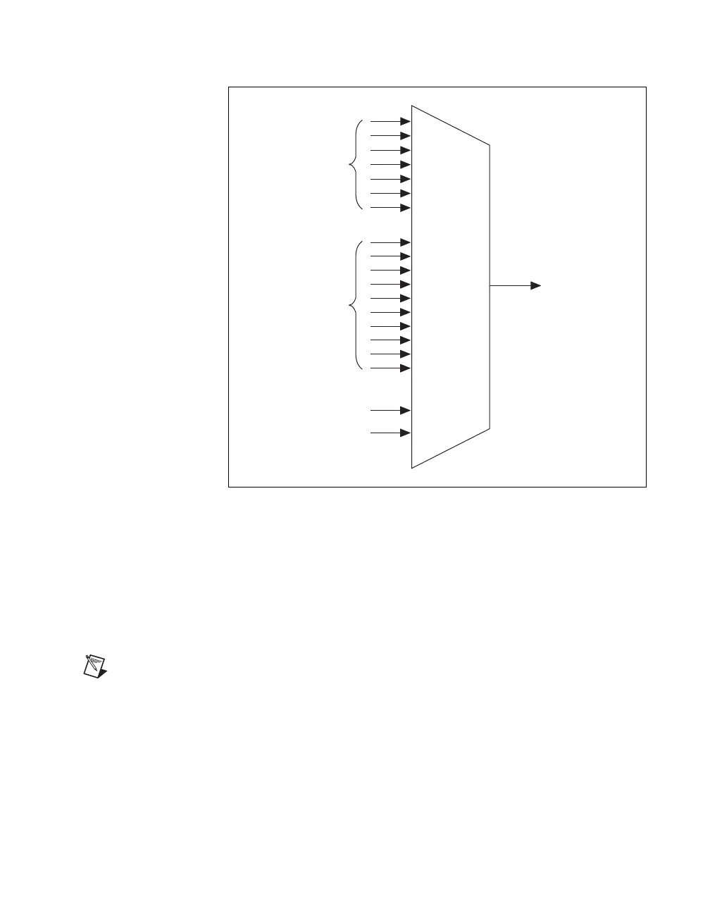
Figure 7-1. ai/ConvertClock Signal Routing
Figure 7-1 shows that ai/Convert Clock can be generated from a number of
sources, including the external signals RTSI <0..6> (PCI and PXI buses
only) and PFI <0..9> and the internal signals, Onboard Clock and
Ctr0InternalOutput.
On PCI and PXI devices, many of these timing signals are also available as
outputs on the PFI pins.
Note The Master Timebase signal can only be accepted as an external signal over RTSI.
Refer to the
Device and RTSI Clocks section of Chapter 8, Real-Time System Integration
Bus (RTSI), for information about routing this signal.
RTSI Trigger <0..6>
PFI <0..9>
ai/ConvertCloc
Onboard Clock
Ctr0InternalOutput

 Loading...


