Chapter 3 Analog Output
© National Instruments Corporation 3-11 E Series User Manual
Using an Analog Source
When you use an analog trigger source, the samples are paused when the
Analog Comparison Event signal is at a high level. Refer to Chapter 10,
Triggering, for more information on analog triggering.
AO Sample Clock Signal
You can use the AO Sample Clock (ao/SampleClock) signal to initiate AO
samples. Each sample updates the outputs of all the DACs.
The source of the ao/SampleClock signal can be internal or external. You
can specify whether the DAC update begins on the rising edge or falling
edge of the ao/SampleClock signal.
Using an Internal Source
By default, ao/SampleClock is created internally by dividing down the
ao/SampleClockTimebase.
Several other internal signals can be routed to the sample clock. Refer to
Device Routing in MAX in the NI-DAQmx Help or the LabVIEW 8.x Help
for more information.
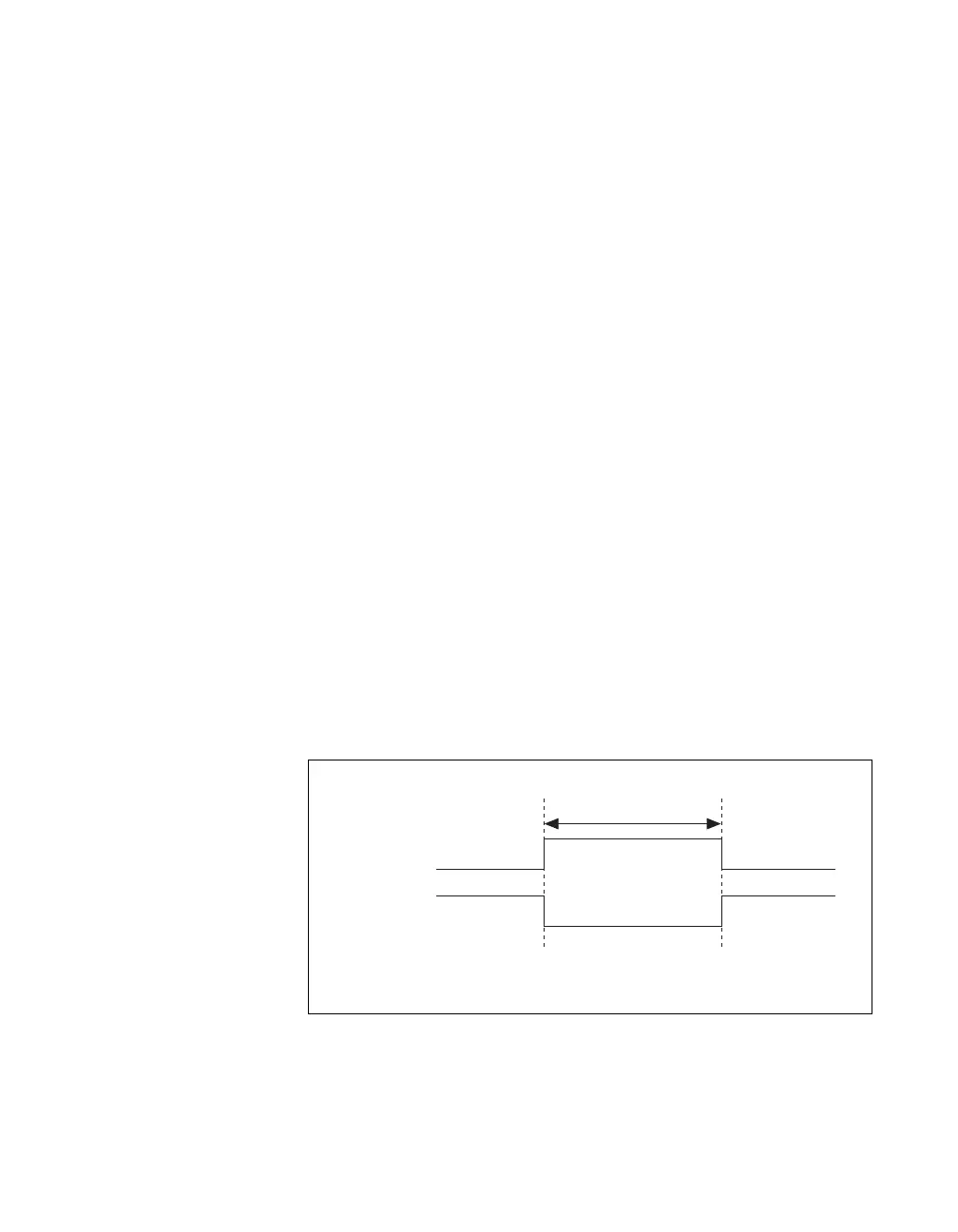
Using an External Source
You can use a signal connected to any PFI or RTSI <0..6> pin as the source
of ao/SampleClock. Figure 3-8 shows the timing requirements of the
ao/SampleClock source.
Figure 3-8. ao/SampleClock Source Timing Requirements
Rising-Edge
Polarity
Falling-Edge
Polarity
t
w
t
w
= 10 ns minimum

 Loading...


