Chapter 3 Analog Output
© National Instruments Corporation 3-9 E Series User Manual
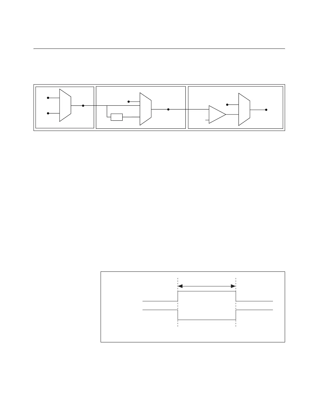
Waveform Generation Timing Signals
There is one AO Sample Clock that causes all AO channels to update
simultaneously. Figure 3-5 summarizes the timing and routing options
provided by the analog output timing engine.
Figure 3-5. Analog Output Timing Engine
AO Start Trigger Signal
You can use the AO Start Trigger (ao/StartTrigger) signal to initiate a
waveform generation. If you do not use triggers, you begin a generation
with a software command.
Using a Digital Source
To use ao/StartTrigger, specify a source and an edge. The source can be an
external signal connected to any PFI or RTSI <0..6> pin. The source can
also be one of several internal signal on your DAQ device. Refer to Device
Routing in MAX in the NI-DAQmx Help or the LabVIEW 8.x Help for more
information.
Figure 3-6 shows the timing requirements of the ao/StartTrigger digital
source.
Figure 3-6. ao/StartTrigger Digital Source Timing Requirements
RTSI 7
20 MHz
Timebase
÷
200
Master
Timebase
Onboard
Clock
PFI 0–9,
RTSI 0–6
ao/SampleClock
Timebase
Onboard
Clock
Divisor
ao/SampleClock
Ctr1InternalOutput
PFI 0–9,
RTSI 0–6
÷
Rising-Edge
Polarity
Falling-Edge
Polarity
t
w
t
w
= 10 ns minimum

 Loading...


