Chapter 2 Analog Input
E Series User Manual 2-40 ni.com
Figure 2-27 shows the relationship of the ai/SampleClock signal to the
ai/StartTrigger signal.
Figure 2-27. ai/SampleClock and ai/StartTrigger
AI Sample Clock Timebase Signal
Any PFI can externally input the AI Sample Clock Timebase
(ai/SampleClockTimebase) signal, which is not available as an output on
the I/O connector. The ai/SampleClockTimebase is divided down to
provide the Onboard Clock source for the ai/SampleClock. You can
configure the polarity selection for ai/SampleClockTimebase as either
rising or falling edge.
The maximum allowed frequency is 20 MHz, with a minimum pulse width
of 23 ns high or low. There is no minimum frequency limitation.
The 20MHzTimebase or the 100kHzTimebase generates
ai/SampleClockTimebase unless you select some external source.
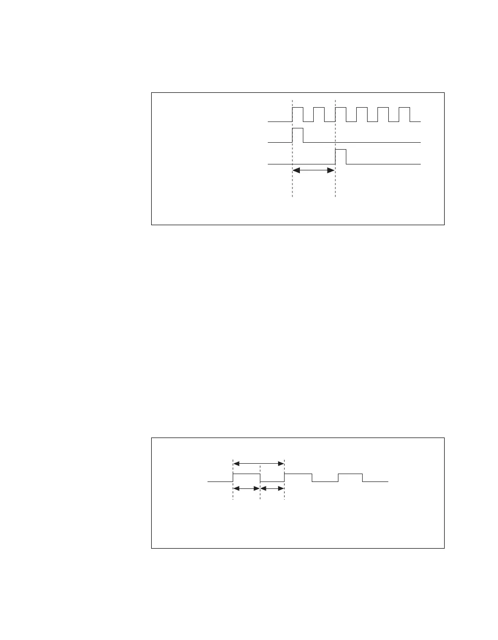
Figure 2-28 shows the timing requirements for ai/SampleClockTimebase.
Figure 2-28. ai/SampleClockTimebase Timing Requirements
ai/StartTrigger
ai/SampleClock
ai/SampleClockTimebase
Delay
From
Start
Trigger
t
p
= 50 ns minimum
t
w
= 23 ns minimum
t
w
t
w
t
p

 Loading...


