Chapter 2 Analog Input
© National Instruments Corporation 2-43 E Series User Manual
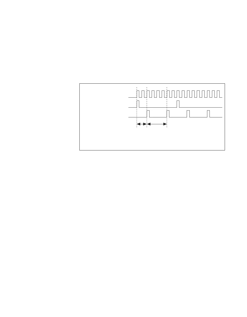
Using a Delay from Sample Clock to Convert Clock
When using an internally generated ai/ConvertClock, you can also specify
a configurable delay from the ai/SampleClock to the first ai/ConvertClock
pulse within the sample. By default, this delay is two ticks of the
ai/ConvertClockTimebase signal.
Figure 2-31 shows the relationship of the ai/SampleClock signal to the
ai/ConvertClock signal.
Figure 2-31. ai/SampleClock and ai/ConvertClock
Other Timing Requirements
The sample and conversion level timing of the DAQ-STC work such that
clock signals are gated off unless the proper timing requirements are met.
For example, the device ignores both the ai/SampleClock and
ai/ConvertClock until it receives a valid ai/StartTrigger signal. Once the
device recognizes an ai/SampleClock pulse, it ignores subsequent
ai/SampleClock pulses until it receives the correct number of
ai/ConvertClock pulses.
Similarly, the device ignores all ai/ConvertClock pulses until it recognizes
an ai/SampleClock pulse. Once the device receives the correct number of
ai/ConvertClock pulses, it ignores subsequent ai/ConvertClock pulses until
it receives another ai/SampleClock. Figure 2-32 shows timing sequences
for a four-channel acquisition and demonstrate proper and improper
sequencing of the ai/SampleClock and ai/ConvertClock signals.
ai/ConvertClockTimebase
ai/SampleClock
ai/ConvertClock
Delay
From
Sample
Clock
Convert
Period

 Loading...


