Chapter 2 Theory of Operation
PCI E Series RLPM 2-8
©
National Instruments Corporation
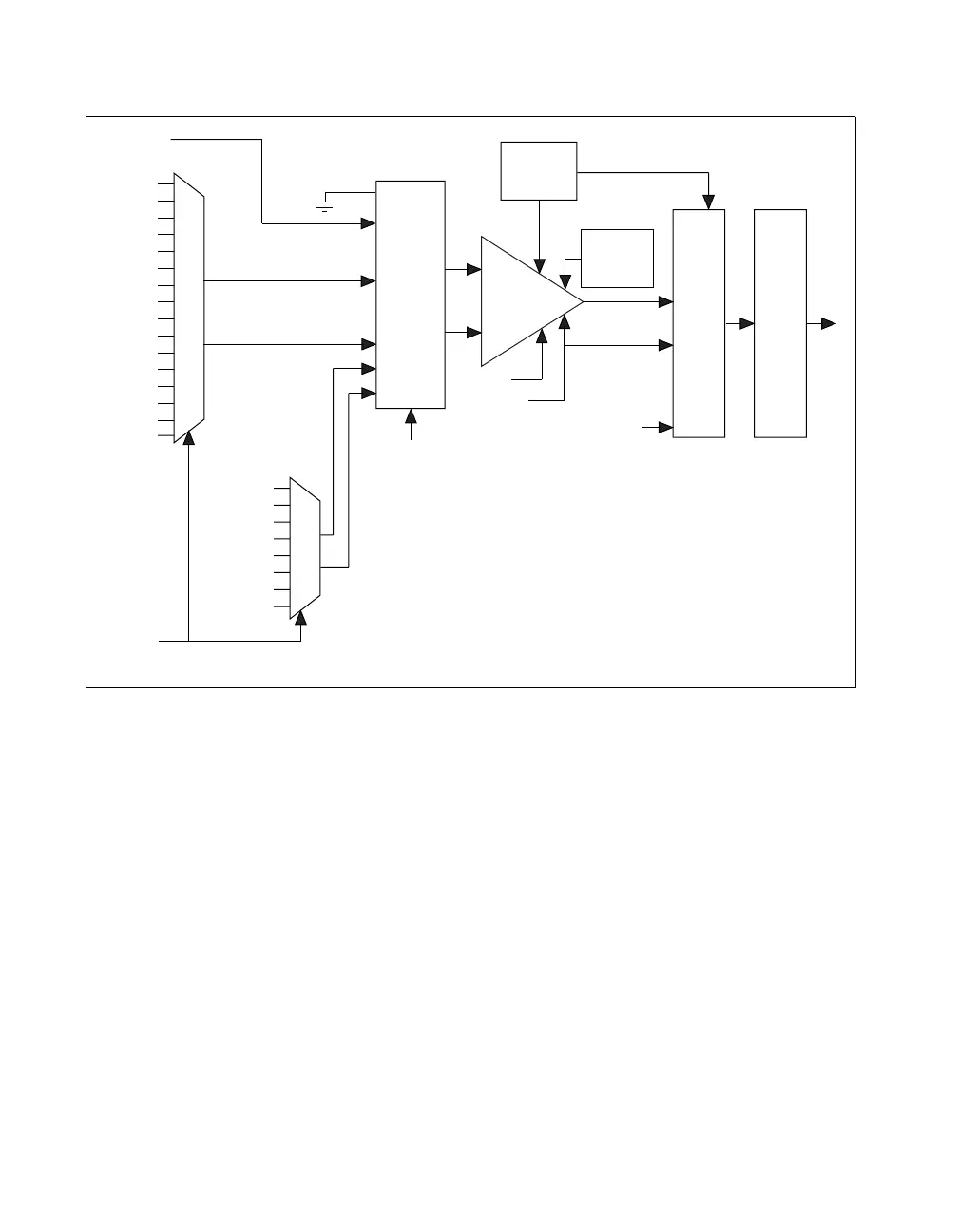
Figure 2-7. Analog Input and Data Acquisition Circuitry Block Diagram
Analog Input Circuitry
The general model for analog input on the PCI E Series boards
includes input multiplexer, multiplexer mode selection switches,
a software-programmable gain instrumentation amplifier, calibration
hardware, a sampling ADC, a 16-bit wide data FIFO, and a configuration
memory.
The configuration memory defines the parameters to use for each
conversion. Each entry in the configuration memory includes channel type,
channel number, bank, gain, polarity, dither, general trigger, and last
channel. The configuration memory is a 512-entry deep FIFO that is
initialized prior to the start of the acquisition sequence. It can be
incremented after every conversion, allowing the analog input
configuration to vary on a per conversion basis. Once the FIFO is empty,
Calibration
DACs
Mode
Selection
Dither
Convert
ADC FIFO
ACH0
AISense
Input Multiplexer
Cal Mux
AIGND
Gain
PGIA
Polarity
Channel
Type
Channel
Number
Calibration
Sources
ACH1
ACH2
ACH3
ACH4
ACH5
ACH6
ACH7
ACH8
ACH9
ACH10
…
…
…
…
ACH15*
*ACH63 for PCI-6071E, PCI-6031E, and PCI-6033E

 Loading...


