Chapter 4 Programming
©
National Instruments Corporation 4-59 PCI E Series RLPM
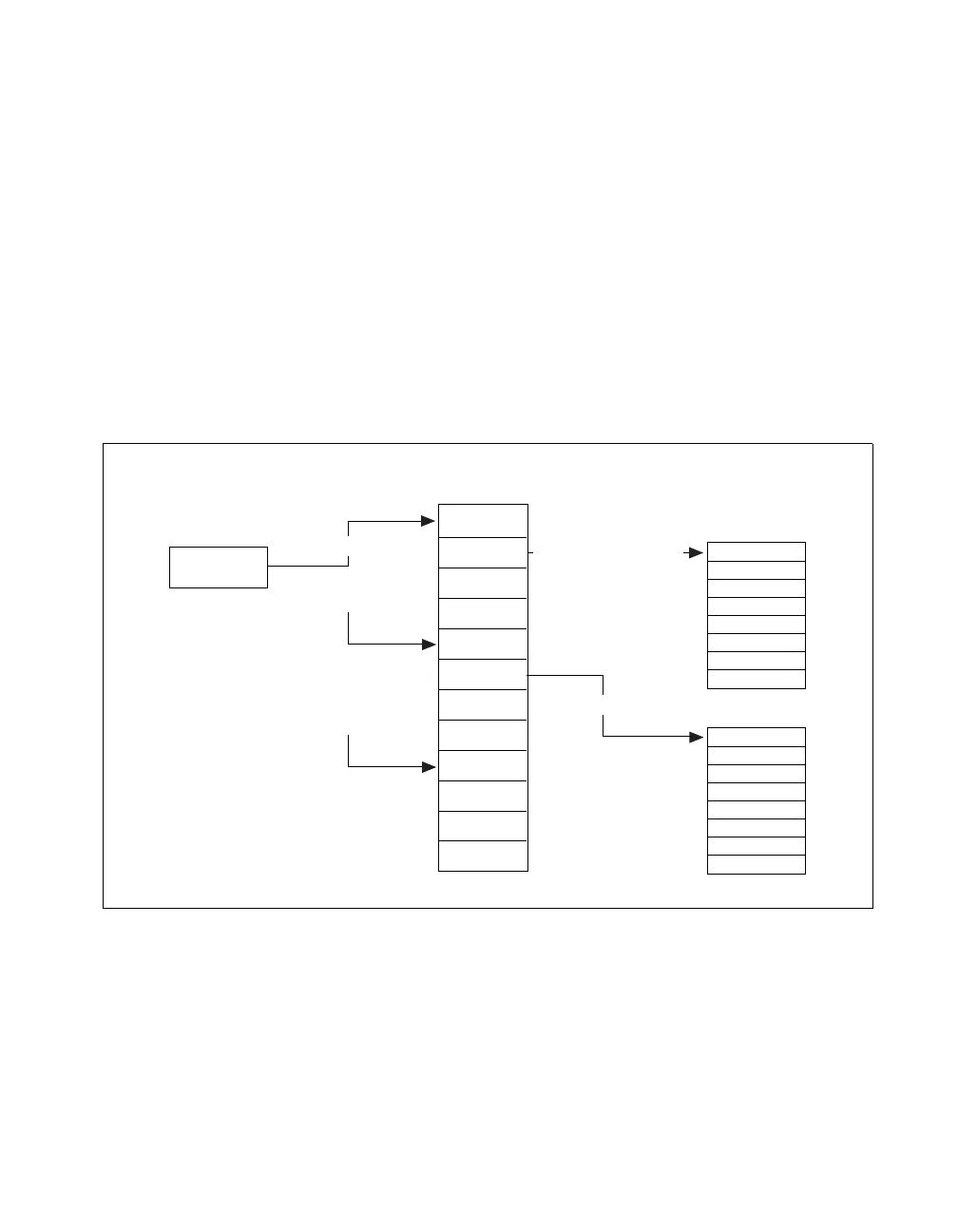
of transfer bytes for each buffer; MAR (Memory Address Register) stores
the buffer’s physical address; DAR (Device Address Register) stores
default values for simple operation; LKAR (Link Address Register) stores
the physical address of the next node.
Before beginning the DMA transfers, LKAR must be loaded with the
physical address of the first node since the MITE needs to have an entry
point to access the link chain. After arming the DMA transfer, the MITE
goes through the link chain and loads the buffer’s physical address into
MAR. Then the MITE transfers data from the FIFO to the buffers or from
the buffer to the output port. This process continues until the MITE reaches
the empty node, the node which contains all zeros.
Figure 4-3 illustrates the basic operation of the Link Chain Mode.
Figure 4-3. DMA Link Chaining Mode Structure
LKAR
TCR
MAR
DAR
LKAR
TCR
MAR
DAR
LKAR
0 (Last Link)
0
0
0
Use Physical Address
Use Physical Address
Use Physical Address
Buffer 0
Use Physical Address
Use Physical Address
Buffer 1
Link Chain

 Loading...


