EasyManuals Logo

National Instruments PXI Series User Manual

National Instruments PXI Series
89 pages
To Next Page IconTo Next Page
To Previous Page IconTo Previous Page
Page #54 background imageLoading...
Page #54 background image
Chapter 3 I/O Information
NI PXI-8109 User Manual 3-10 ni.com
Trigger
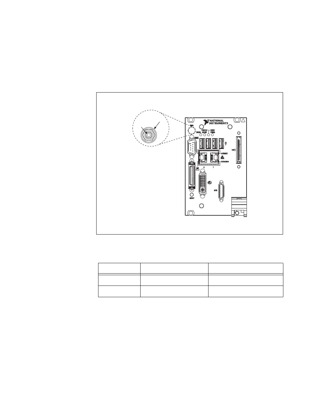
The TRIG connector is the software-controlled trigger connection for
routing PXI triggers to or from the backplane trigger bus.
Figure 3-7 shows the TRIG connector location on the NI PXI-8109.
Table 3-8 lists and describes the trigger connector signals.
Figure 3-7. TRIG Connector Location and Pinout
Table 3-8. TRIG Connector Signals
Pin Signal Name Signal Description
1 TRIG Trigger
2 (Shield) GND Ground
1
2
NI PXI-8109
Embedded Controller

Table of Contents

Other manuals for National Instruments PXI Series

Questions and Answers:

Question and Answer IconNeed help?

Do you have a question about the National Instruments PXI Series and is the answer not in the manual?

National Instruments PXI Series Specifications

General IconGeneral
Form FactorPXI
Slot Count4, 8, 18 slots
CoolingForced air
CompatibilityPXI modules
Operating Temperature0 °C to 55 °C
Relative Humidity10% to 90%, non-condensing
DimensionsVaries depending on the specific chassis model
WeightVaries depending on the specific chassis model

Related product manuals