Chapter 3 I/O Information
© National Instruments 3-7 NI PXI-8109 User Manual
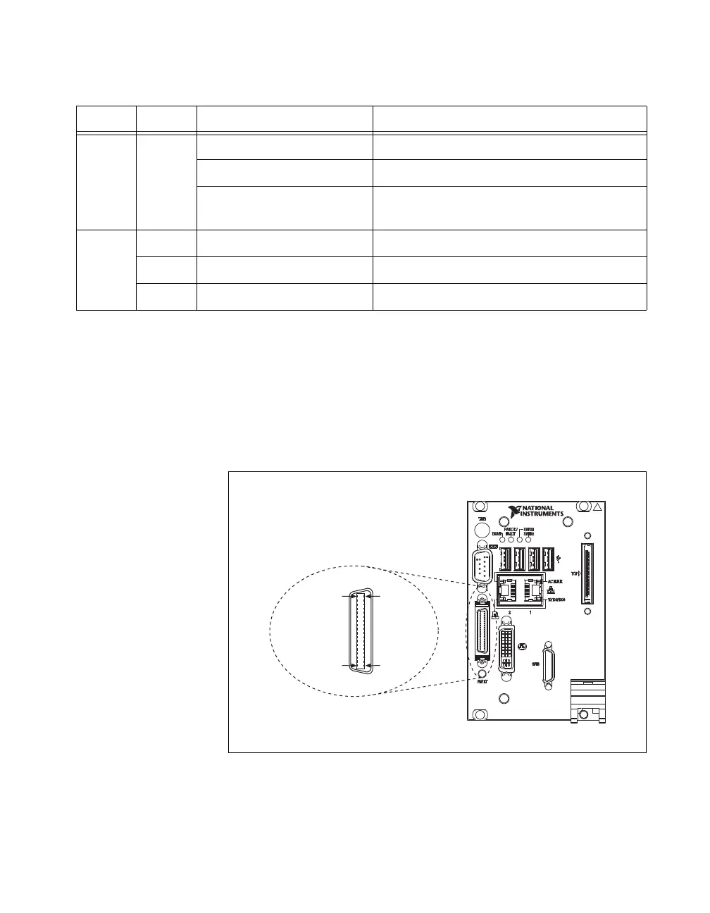
Parallel Port
Figure 3-5 shows the location and pinouts for the IEEE 1284 (parallel)
connector on the NI PXI-8109. Table 3-6 lists and describes the IEEE 1284
connector signals.
Parallel port adapter cables are available from National Instruments,
part number 777169-01.
Figure 3-5. Parallel Port Connector Location and Pinout
Table 3-5. 10/100/1000 LAN Connector LED States
LED Color LED State Condition
Top Green
Off LAN link is not established.
On (steady state) LAN link is established.
On (brighter and pulsing) The controller is communicating with
another computer on the LAN.
Bottom
Unlit Off 10 Mbit/sec data rate is selected.
Green On 100 Mbit/sec data rate is selected.
Orange On 1000 Mbit/sec data rate is selected.
NI PXI-8109
Embedded Controller
Parallel Port
18
1
36
19
 Loading...