EasyManuals Logo
Home>National Instruments>Chassis>PXI Series

National Instruments PXI Series User Manual

National Instruments PXI Series
89 pages
To Next Page IconTo Next Page
To Previous Page IconTo Previous Page
Page #53 background imageLoading...
Page #53 background image
Chapter 3 I/O Information
© National Instruments 3-9 NI PXI-8109 User Manual
Universal Serial Bus
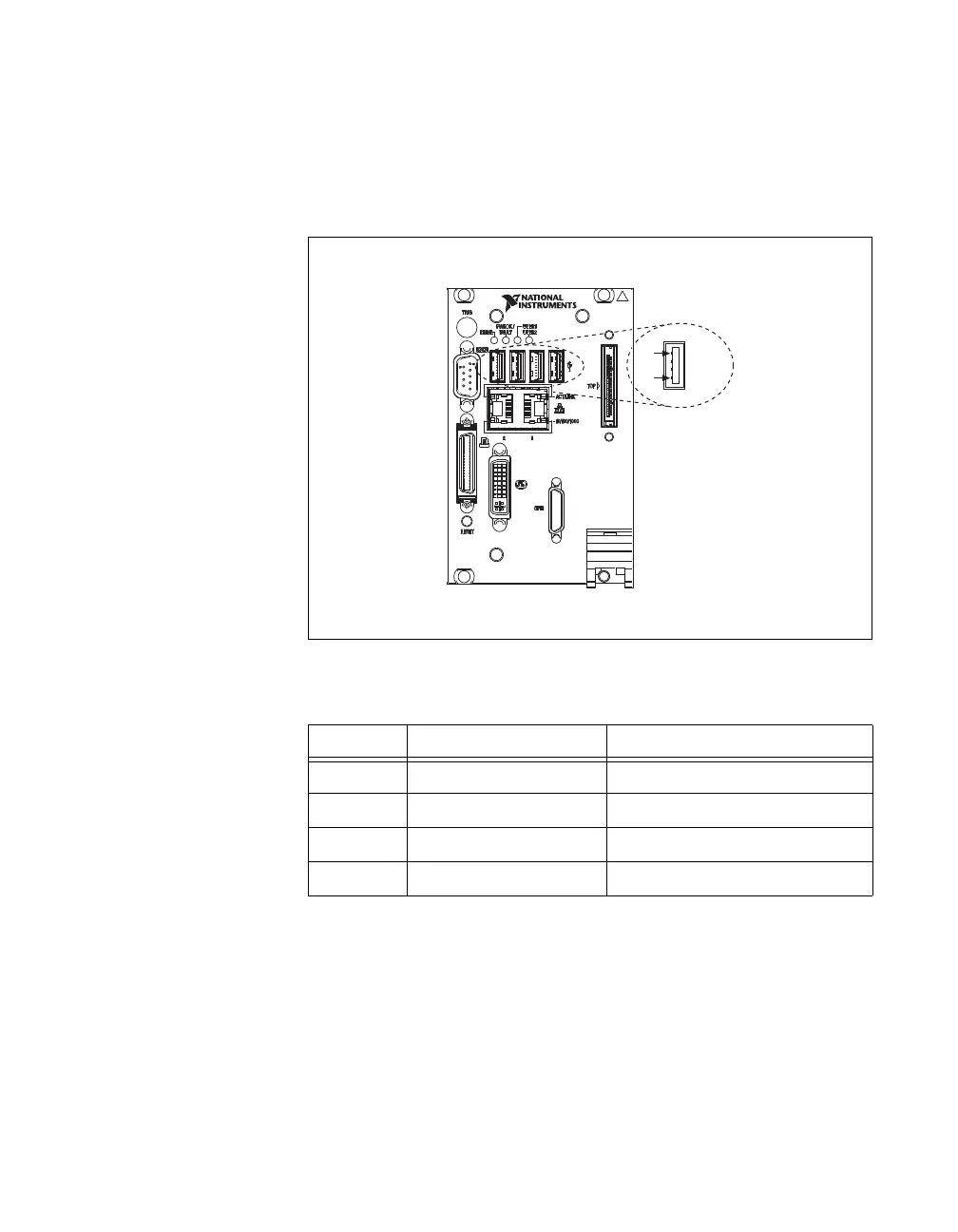
Figure 3-6 shows the location and pinouts for the Universal Serial Bus
(USB) connectors on the NI PXI-8109. Table 3-7 lists and describes the
USB connector signals.
Figure 3-6. USB Connector Location and Pinout
Table 3-7. USB Connector Signals
Pin Signal Name Signal Description
1 VCC Cable Power (+5 V)
2 D– USB Data –
3 D+ USB Data +
4 GND Ground
USB
4
1
NI PXI-8109
Embedded Controller

Table of Contents

Other manuals for National Instruments PXI Series

Questions and Answers:

Question and Answer IconNeed help?

Do you have a question about the National Instruments PXI Series and is the answer not in the manual?

National Instruments PXI Series Specifications

General IconGeneral
BrandNational Instruments
ModelPXI Series
CategoryChassis
LanguageEnglish

Related product manuals