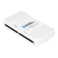
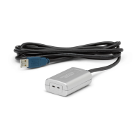
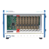
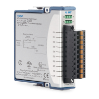
Do you have a question about the National Instruments USB-6210 and is the answer not in the manual?
Steps for installing NI-DAQmx software and drivers for the device.
Information on how to install USB devices and the DAQ device.
Procedure for calibrating the device after installation for optimal accuracy.
Diagrams showing the pin assignments for the device's I/O connectors.
Guidance on applying labels to device terminals for clear signal identification.
Methods for providing strain relief for the USB cable connection.
Options for desktop, DIN rail, or panel mounting the USB-621x device.
Information on using a security cable to attach an antitheft device.
Overview of the DAQ hardware's functions: digitizing signals, D/A conversions, I/O control.
Details on the DAQ-STC2 digital engine and its key features.
Explanation of the USB-621x's internal circuitry for correcting gain and offset errors.
Information on preparing signals for accurate data acquisition using external components.
Description of common sensors and the need to convert their signals for DAQ devices.
Overview of available cable and accessory options for USB-621x devices.
Guidance on using NI-DAQmx driver software and examples for device programming.
Detailed descriptions of signals found on the device's I/O connectors.
Information on using the +5 V power terminals as either an output or input.
Requirements for connecting the USB chassis to earth ground for EMC compliance.
Step-by-step instructions for replacing the device's fuse.
Explanation of the device status indicated by the PWR/ACT LED.
How input range selection affects device resolution and accuracy.
Configuration options for differential, referenced single-ended, and non-referenced single-ended modes.
Software methods for setting analog input ground references using DAQ Assistant or C API.
Factors affecting accuracy in multichannel scanning, such as settling time.
Techniques for acquiring analog input data: software-timed vs. hardware-timed.
How digital triggers initiate analog input acquisition actions.
Best practices for wiring analog input signals to minimize noise and maximize accuracy.
Overview of signals controlling analog input timing, including sample and convert clocks.
Function and configuration of the AI Sample Clock signal for initiating measurements.
Function and configuration of the AI Convert Clock signal for A/D conversions.
Use of the AI Start Trigger signal to begin a measurement acquisition.
Use of the AI Reference Trigger signal for buffering data relative to a trigger.
How the AI Pause Trigger signal pauses and resumes measurement acquisition.
Recommended input configurations for connecting signals to specific devices.
Guidelines for connecting floating signal sources to the device.
Guidelines for connecting ground-referenced signal sources to the device.
The defined voltage range for analog output channels on USB-621x devices.
Techniques to reduce unwanted signal glitches during DAC output generation.
Methods for generating analog output data: software-timed vs. hardware-timed.
How digital triggers initiate analog output operations.
How to connect analog output signals to the device's AO channels.
Overview of signals controlling analog output timing, including start and sample clocks.
Use of the AO Start Trigger signal to initiate waveform generation.
How the AO Pause Trigger signal pauses waveform generation.
Function and configuration of the AO Sample Clock signal for initiating AO samples.
Use of the AO Sample Clock Timebase signal for clocking analog output.
Guidance for setting up analog output applications in software.
Digital I/O capabilities for USB-6210/6211/6215/6218 devices.
Using static digital I/O lines for monitoring or controlling digital signals.
Understanding and avoiding I/O fault conditions for protection.
Methods to increase the internal current limit for digital outputs.
How to connect digital I/O signals to the device's I/O connector.
Software guidance for setting up digital I/O applications on specific devices.
Digital I/O capabilities for USB-6212/6216 devices.
Using static digital I/O lines for monitoring or controlling digital signals.
Understanding and avoiding I/O fault conditions for protection.
Configuring power-up states for PFI and DIO lines on specific devices.
Methods to increase the internal current limit for digital outputs.
How to connect digital I/O signals to the device's I/O connector.
Software guidance for setting up digital I/O applications on specific devices.
Routing external timing signals to PFI terminals for various functions.
Routing timing signals from the device to PFI output terminals.
Configuring PFI terminals for static digital input or output operations.
How to connect external signals to PFI input terminals.
Enabling programmable debouncing filters on PFI signals.
Protection mechanisms for digital and PFI signals against voltage and current.
Configuring power-up states for PFI and DO lines.
Overview of counter input functions like edge counting and pulse width.
Measuring the width of input pulses using counter functionality.
Measuring the period of input signals using counter functionality.
Measuring half-periods of input signals using counter functionality.
Methods for measuring signal frequency using counters.
Measuring position using encoders with counter functionality.
Overview of counter output functions like pulse and train generation.
Signals that control counter timing operations.
Default terminal assignments for counter/timer signals.
Triggering actions that can be configured for counter operations.
Additional counter functionalities like sample clock, filters, and prescaling.
Explanation of digital isolators and their role in data acquisition.
Advantages of using isolated DAQ devices, including improved rejection and accuracy.
Techniques for minimizing common-mode noise in isolated systems.
Methods for establishing AC return paths to reduce noise.
Description of measurement systems where the isolated front end is not earth grounded.
Description of measurement systems where the isolated front end connects to earth ground.
Usage of the 80 MHz timebase as a signal source for counters.
Usage of the 20 MHz timebase for AI and AO timing signals.
Usage of the 100 kHz timebase for AI and AO timing signals.
High-performance data transfer method using USB bulk transfers.
Overview of USB data transfer mechanisms: USB Signal Stream and Programmed I/O.
How to switch data transfer mechanisms between USB Signal Streams and programmed I/O.
Generating triggers by specifying a digital signal source and edge.
Pinouts and specific information for the USB-6210 device.
Pinouts and specific information for USB-6211 and USB-6215 devices.
Pinouts for the USB-6212/6216 Screw Terminal devices.
Pinouts for the USB-6212/6216 Mass Termination devices.
Pinouts for the USB-6212/6216 BNC devices.
Pinouts for the USB-6218 Screw Terminal devices.
Pinouts for the USB-6218 BNC devices.
Common issues and solutions for analog input problems like crosstalk and drift.
Common issues and solutions for analog output problems like signal glitches.
Resources for technical assistance including KnowledgeBase and forums.
Information on training programs, eLearning, and certification.
Services offered by National Instruments Alliance Partners for system integration.
Compliance statements for electromagnetic compatibility and product safety.
Information on obtaining calibration certificates for products.
| Analog Input Resolution | 16 bits |
|---|---|
| Sampling Rate | 250 kS/s (aggregate) |
| Analog Output Channels | 2 |
| Analog Output Resolution | 16 bits |
| Analog Output Range | ±10 V |
| Counter/Timers | 2 |
| Interface | USB |
| Analog Input Channels | 16 (single-ended) or 8 (differential) |
| Analog Input Range | ±10 V |
| Digital I/O Channels | 24 |
| Operating Temperature Range | 0 °C to 50 °C |
| Storage Temperature Range | -20 °C to 70 °C |
