Chapter 8 Counters
© National Instruments Corporation 8-23 NI USB-621x User Manual
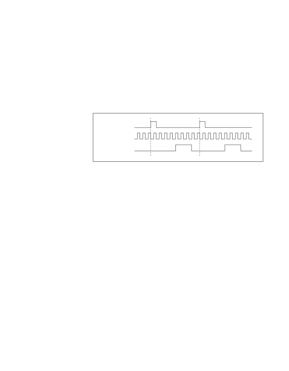
You can route the Start Trigger signal to the Gate input of the counter. You
can specify a delay from the Start Trigger to the beginning of each pulse.
You also can specify the pulse width. The delay and pulse width are
measured in terms of a number of active edges of the Source input.
The counter ignores the Gate input while a pulse generation is in progress.
After the pulse generation is finished, the counter waits for another Start
Trigger signal to begin another pulse generation.
Figure 8-24 shows a generation of two pulses with a pulse delay of five and
a pulse width of three (using the rising edge of Source).
Figure 8-24. Retriggerable Single Pulse Generation
For information about connecting counter signals, refer to the Default
Counter/Timer Pinouts section.
Pulse Train Generation
Continuous Pulse Train Generation
This function generates a train of pulses with programmable frequency and
duty cycle. The pulses appear on the Counter n Internal Output signal of the
counter.
You can specify a delay from when the counter is armed to the beginning
of the pulse train. The delay is measured in terms of a number of active
edges of the Source input.
You specify the high and low pulse widths of the output signal. The pulse
widths are also measured in terms of a number of active edges of the Source
input. You also can specify the active edge of the Source input (rising or
falling).
The counter can begin the pulse train generation as soon as the counter is
armed, or in response to a hardware start trigger. You can route the Start
Trigger to the Gate input of the counter.
SOURCE
GATE
(Start Trigger)
OUT

 Loading...


