Chapter 8 Counters
© National Instruments Corporation 8-27 NI USB-621x User Manual
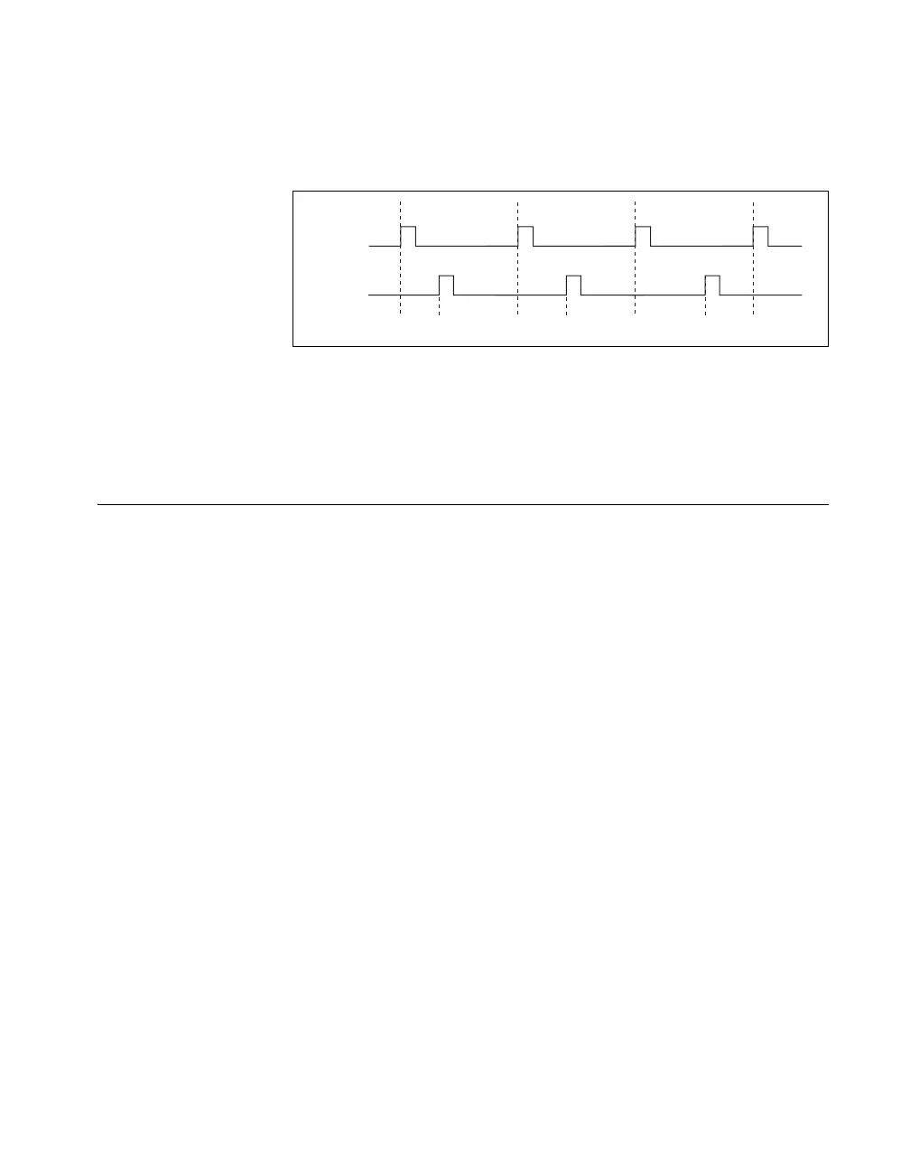
frequency of the system. Figure 8-29 shows an example of pulse generation
for ETS; the delay from the trigger to the pulse increases after each
subsequent Gate active edge.
Figure 8-29. Pulse Generation for ETS
For information about connecting counter signals, refer to the Default
Counter/Timer Pinouts section.
Counter Timing Signals
USB-621x devices feature the following counter timing signals:
• Counter n Source Signal
• Counter n Gate Signal
• Counter n Aux Signal
• Counter n A Signal
• Counter n B Signal
• Counter n Z Signal
• Counter n Up_Down Signal
• Counter n HW Arm Signal
• Counter n Internal Output Signal
• Counter n TC Signal
• Frequency Output Signal
In this section, n refers to either Counter 0 or 1. For example, Counter n
Source refers to two signals—Counter 0 Source (the source input to
Counter 0) and Counter 1 Source (the source input to Counter 1).
OUT
D1 D2 = D1 + ΔD D3 = D1 + 2ΔD
GATE
 Loading...


