Chapter 6 Digital I/O
© National Instruments Corporation 6-3 NI USB-621x User Manual
Increasing Current Drive on USB-6210/6211/6215/6218 Devices
The total internal current limit for digital outputs and power drawn from the
+5 V terminals is 50 mA. You can increase this internal current limit by
supplying an external +5 V supply. Refer to the +5 V Power as an Input
section of Chapter 3, Connector and LED Information.
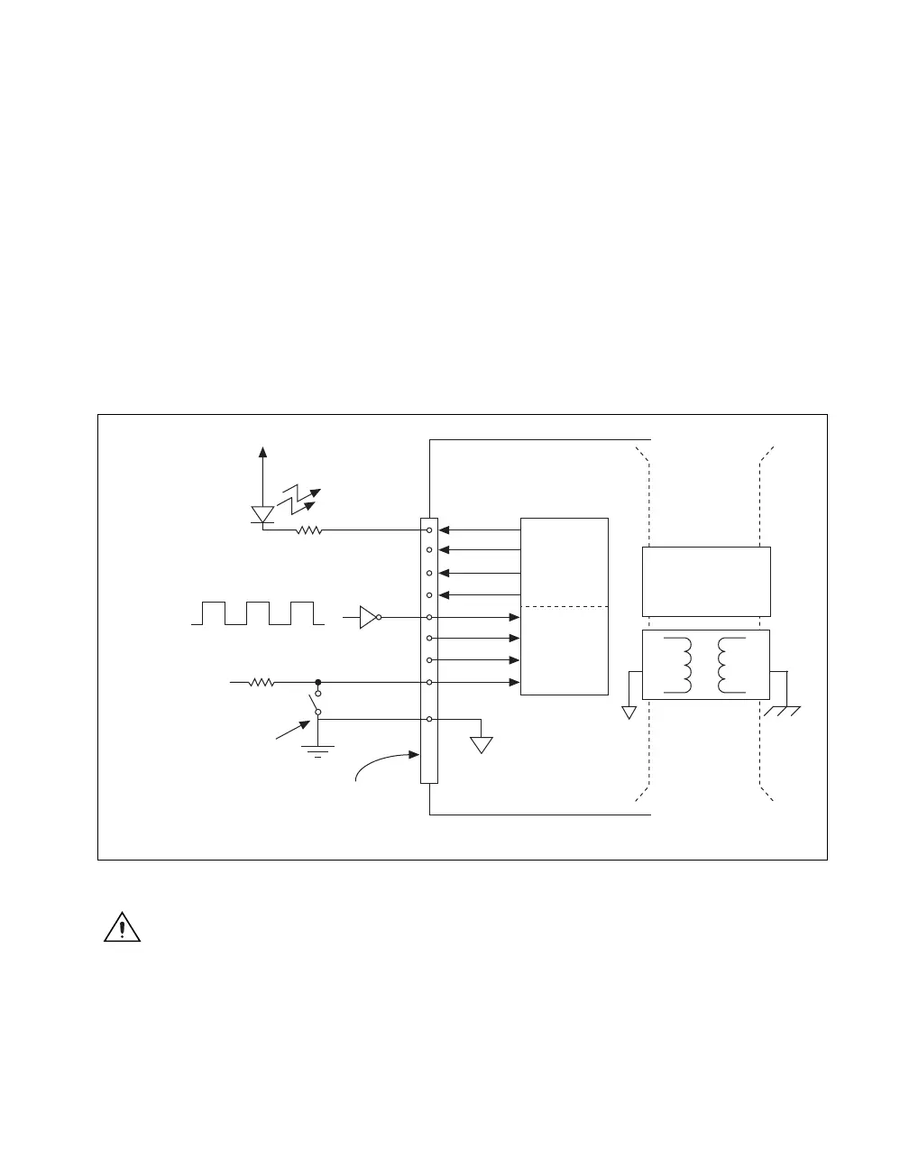
Connecting Digital I/O Signals on USB-6210/6211/6215/6218 Devices
The DI and DO signals, P0.<0..7> and P1.<0..7> are referenced to D GND.
Digital input applications include receiving TTL signals and sensing
external device states, such as the state of the switch shown in the figure.
Digital output applications include sending TTL signals and driving
external devices, such as the LED shown in Figure 6-2.
Figure 6-2. USB-6210/6211/6215/6218 Digital I/O Connections
Caution
Exceeding the maximum input voltage ratings, which are listed in the
NI USB-621x Specifications, can damage the DAQ device and the computer. NI is not
liable for any damage resulting from such signal connections.
+5
LED
TTL Signal
+5 V
Switch
I/O Connector
D GND
USB-6210/6211/6215/6218 Device
P0.<0..3>
P1.<0..3>
Digital
Isolators
Isolation
Barrier
(USB-6215
and USB-6218
devices only)
When using a
USB-6215/6218,
you must connect
D GND and/or AI GND
to the local ground
on your system.

 Loading...


