NV10LT/NV7.5LT INSTALLATION MANUAL CONNECTING AC POWER
PAGE 2.5.4 VERSION 5.0 2021-03-01
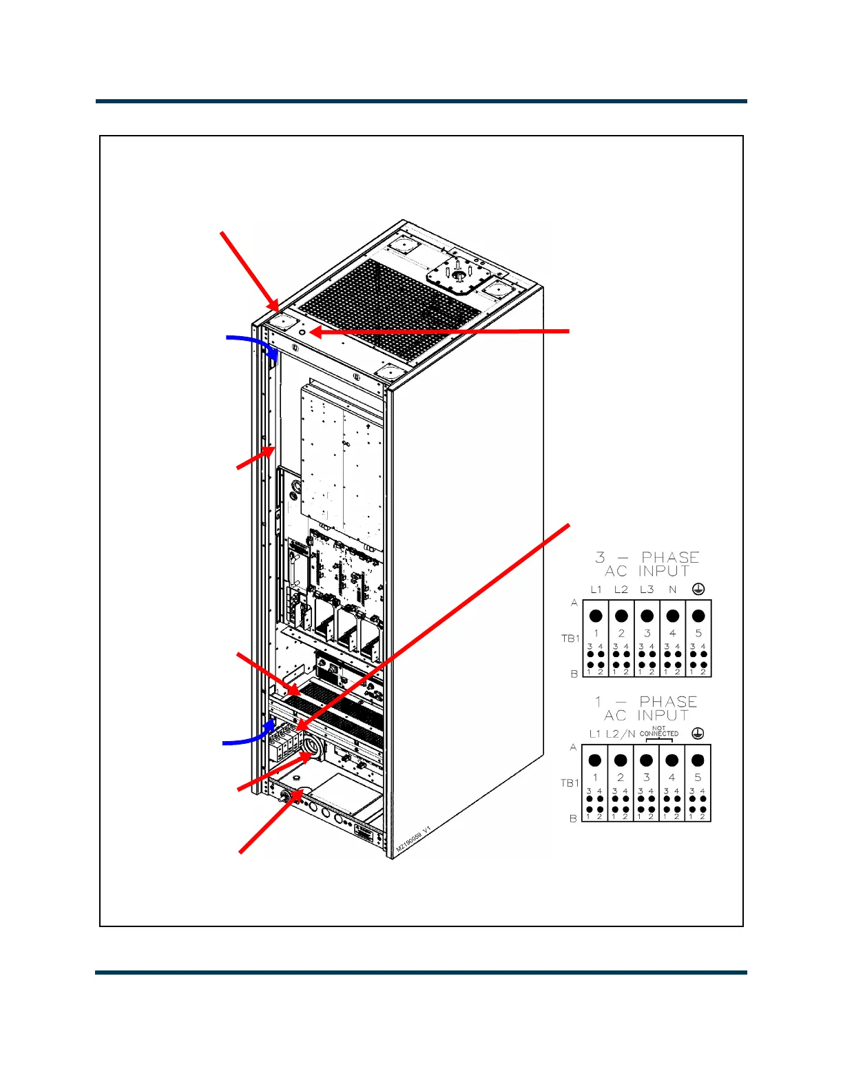
Figure 2.5.1: Ac Mains and UPS Input Routing and Connections
**TOP AC
INPUT ENTRY
TB1
(TB1-1 closest
to the rear)
** AC WIRING ENTRY HOLE HAS A REMOVEABLE PLATE WITH A PRE-CUT 1/4-INCH
DIA HOLE. USE A CHASSIS PUNCH TOOL (e.g., GREENLEE) TO PUNCH DESIRED
HOLE SIZE IN PLATE. REMOVE PLATE (FOUR M4 SCREWS) BEFORE PUNCHING.
CHANNEL
ENTRY POINT
CHANNEL
EXIT POINT
TYRAP ANCHOR
HOLES PROVIDED
FOR ROUTING
WIRE OUTSIDE OF
CHANNEL (typically
not used)
Shown with rear panels removed
FERRITE TOROIDS
L5 (not included on
some transmitters)
BOTTOM AC AND
UPS INPUT ENTRY
(2-in. dia. hole) (not
included on some
transmitters)
GRILLED PANEL
(four M4 screws)
REMOVE THE PLATE TO ACCESS A 2.5-INCH HOLE, IF NECESSARY.
TOP UPS AC
INPUT ENTRY
0.25 in. (0.64 mm)
dia. pilot hole
(punch to desired size)
 Loading...


