VX3 TO VX6 INSTALLATION MANUAL COOLING REQUIREMENTS
VERSION 1.0 2023-08-16 PAGE 1.4.1
SECTION 1.4: COOLING REQUIREMENTS
This section provides information about heating and cooling requirements for the VX3 to VX6
transmitter site. Topics in this section include:
Air Flow in the Transmitter
Cooling - see page 1.4.2
Heating - see page 1.4.2
Air Flow in the Transmitter
The VX3 to VX6 transmitter draws air in through the front, and exhausts air through the rear.
The exciter/controller assembly uses a single, fixed speed fan in the front to cool the pre-amplifier/IPA
and exciter PWB assembly. Airflow is exhausted by grills in the rear of the chassis.
The amplifier assembly uses five (5) fans in the front of the amplifier assembly, which have variable
speeds to maintain optimal cooling vs operating conditions. Airflow is exhausted through grills in the
rear chassis. The three (3) PA power supplies (U1-U3) have their own internal cooling fans to draw cool
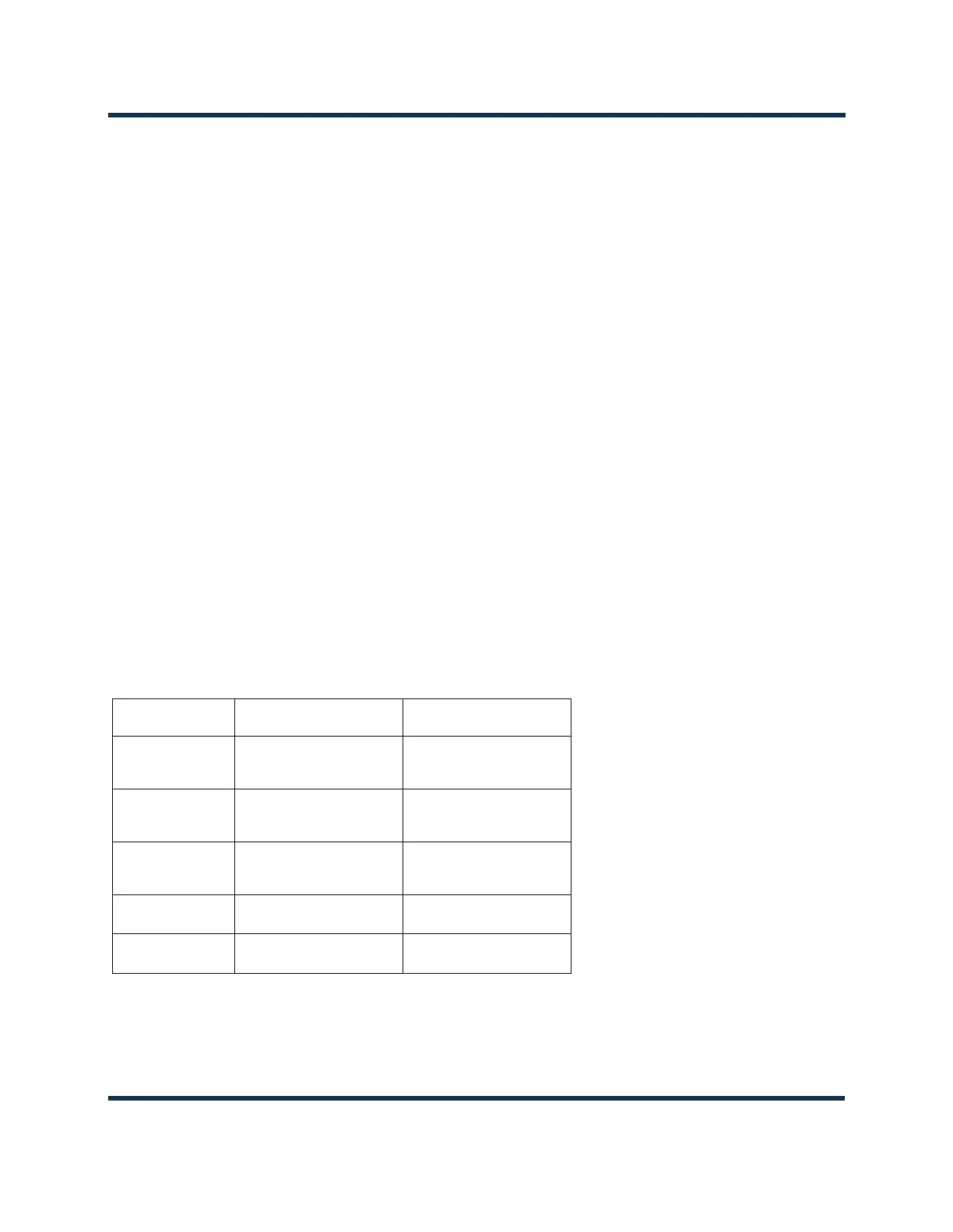
(intake) air through the front of the power supply. See Table 1.4.1 for typical and maximum air flow
requirements.
Table 1.4.1: Transmitter Air Flow Requirements
ASSEMBLY TYPICAL AIRFLOW MAXIMUM AIRFLOW
Exciter/Controller
(fixed fan speed)
30 CFM (51 m
3
/hr) 30 CFM (51 m
3
/hr)
Amplifier (VX3-VX4)
(variable fan speed)
220 CFM (374 m
3
/hr) 335 CFM (569 m
3
/hr)
Amplifier (VX5/VX6)
(variable fan speed)
250 CFM (425 m
3
/hr) 365 CFM (620 m
3
/hr)
System (VX3-VX4)
250 CFM (425 m
3
/hr) 365 CFM (620 m
3
/hr)
System (VX5/VX6)
280 CFM (476 m
3
/hr) 395 CFM (671 m
3
/hr)
 Loading...


