VX3 TO VX6 INSTALLATION MANUAL COMPLETING EXTERNAL CONNECTIONS
VERSION 1.0 2023-08-16 PAGE 1.10.7
Connecting Remote Control/Monitor Wiring
1. Make sure you have completed the planning requirements described in Control and Monitor Wiring
on page 1.8.1 before proceeding.
2. Route all remote control/monitor cables to the rear panel of the exciter/controller assembly.
3. Obtain two ferrite toroids (Nautel Part # LXP38, 19 mm inner diameter) from the ancillary kit.
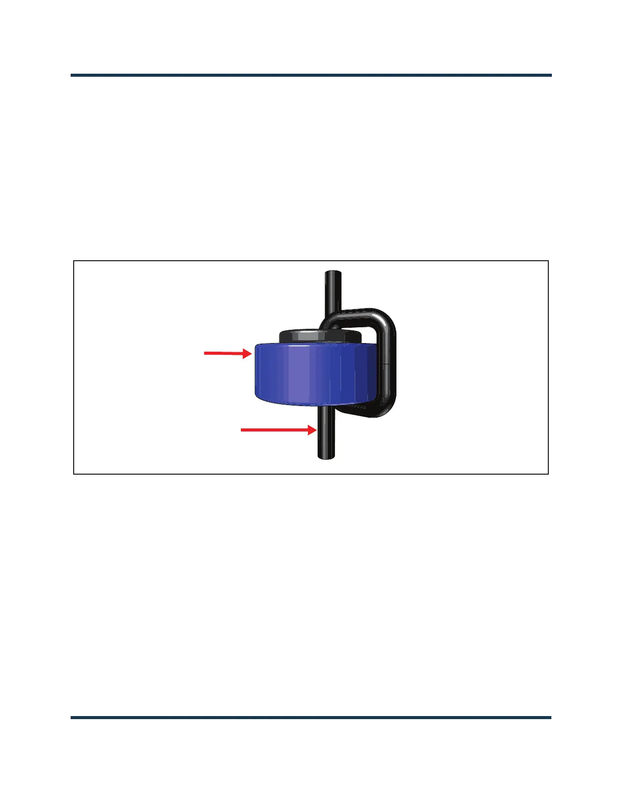
4. Pass all remote control and monitor cables through the ferrite toroids obtained in Step 3. If
practical, wires should pass through a minimum of two times (two turns) (see Figure 1.10.3).
Figure 1.10.3: Passing remote/control monitor wiring through ferrite toroids
5. With the remote control/monitor cables near their destination, cut each wire to the required
length, and install connectors, as necessary.
6. Connect the appropriate control/monitor cable(s) to the REMOTE I/O-A and REMOTE I/O-B D-sub
connectors as described in
Control and Monitor Wiring on page 1.8.1. Nautel provides D-sub mating
connectors (Nautel part #’s JS223 and JS224) and connector shell (Nautel Part # JS225) in the
ancillary kit to facilitate connections to the transmitter, as applicable.
7. For the transmitter’s external interlock control, route a shielded cable to the
INTLK connector. Use
the mating connector (Nautel part # JR52) is supplied in the ancillary kit to facilitate this
connection.
8. For web based control of the transmitter, route an Ethernet (shielded Cat5) cable to the LAN
connector.
Remote Control/Monitor
Cables (to transmitter
rear panel)
LXP38
ferrite toroids
 Loading...


