22
Note: Your machine may not match the image. For reference only.
1. Turn the power off and on.
E614— disconnect and reconnect the AC Adapter from the wall outlet.
E616— turn the Power Switch off and back on.
2. Push QuickStart and verify that the console shows that the default
resistance level is 4.
Disconnect all power and allow to sit for 5 minutes.
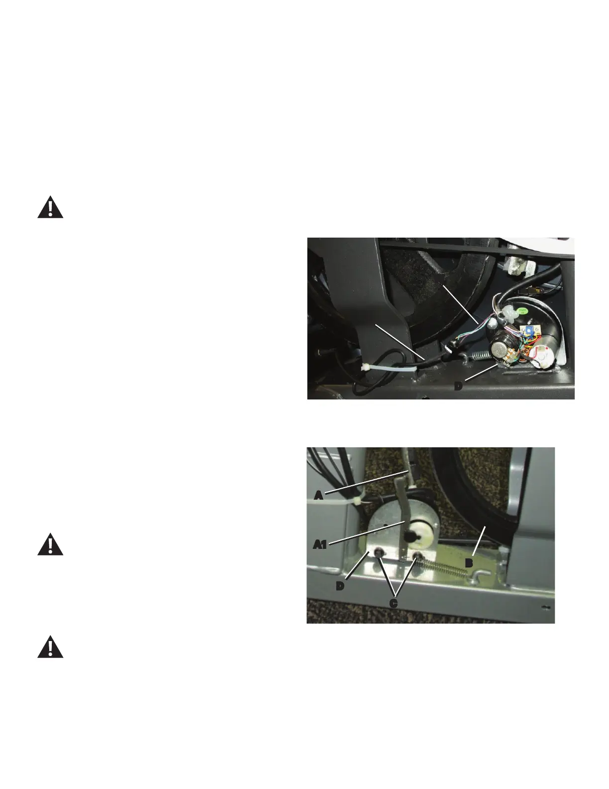
3. Carefully remove the Left Shroud and Right Shroud. (Refer to the
“Replace the Shrouds” procedure.) Turn the Top Shroud to keep it clear
of the pulley assembly. Keep the Power Inlet cable (P) in the Shroud
FRQQHFWHGWRWKHZLULQJKDUQHVV:RQWKHPRWRU'
Note: If it is necessary to remove the Top Shroud, reinstall the
Console and Mast.
4. Insert 2.5” x 10” cardboard between the Brake Magnet (A) and the
Flywheel (B), and tape the cardboard to the Brake Magnet.
Note: Be sure the cardboard covers all of the Brake Magnet.
4. Turn the power on again.
Machine is on. Current is active. There is risk of electrical
shock.
5. Use the console to set the resistance to the highest level. This moves
the Brake Magnet Arm (A1) forward. After the Brake Magnet Arm stops at
the highest resistance level, turn power off.
Disconnect all power and allow to sit for 5 minutes.
6. To adjust the Brake tension, loosen the 2 hex head bolts (C) and
PRYHWKH6HUYR0RWRUDVVHPEO\'XQWLOWKHFORVHVWSRLQWRQWKH%UDNH
Magnet (A) is within 3.0 mm (1/8”) of the Flywheel (B). Tighten the bolts.
NOTICE: It is necessary to remove the shrouds for this procedure. Refer to the “Replace the Shrouds” procedure.
Right side
B
D
A
A1
C
P
W
D
Left side

 Loading...