73
Note: Your machine may not match the image. For reference only.
1. 'LVFRQQHFWDOOSRZHUDQGDOORZWRVLWIRUPLQXWHV
2. Carefully remove the Right Shroud. Refer to the “Replace the
Shrouds” procedure in this manual.
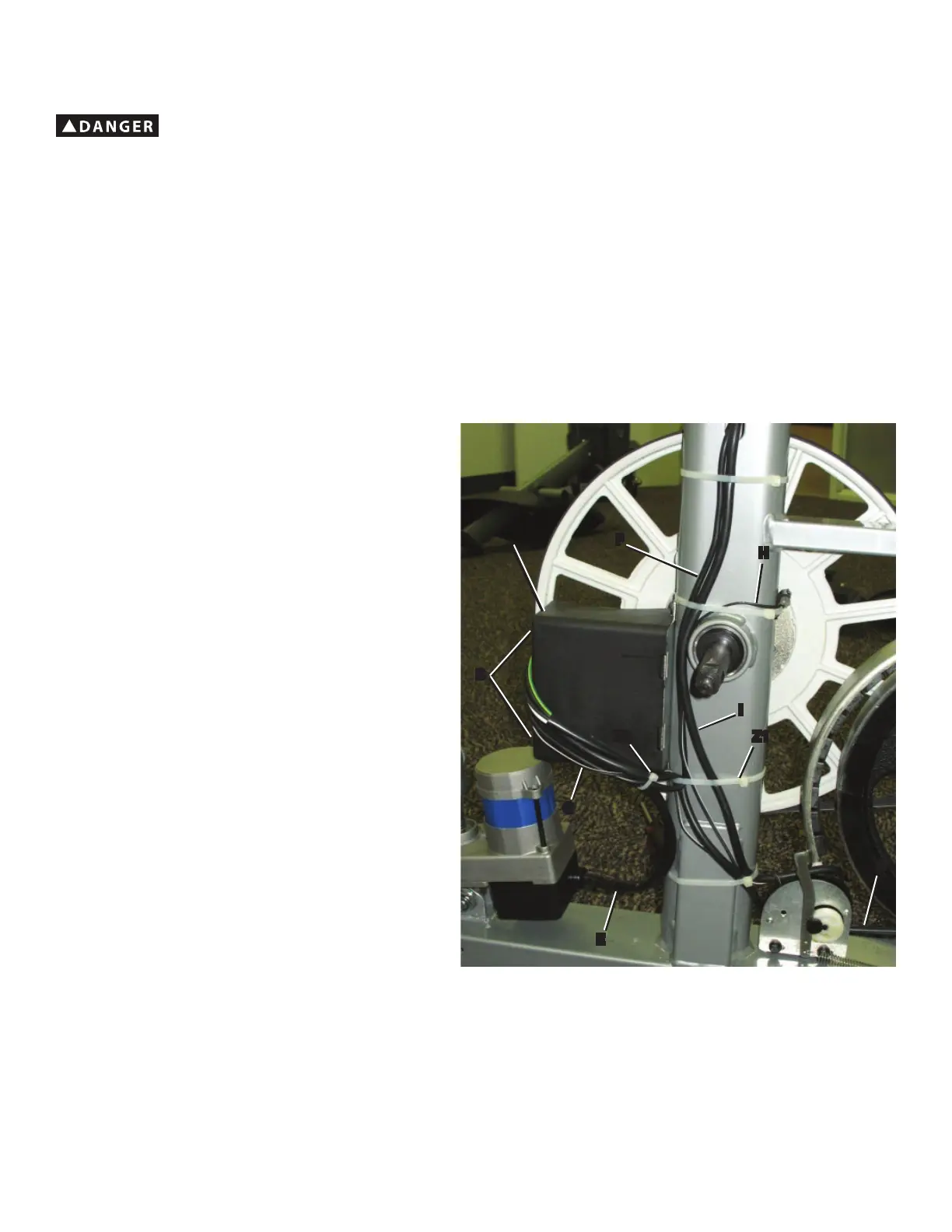
3. Observe the cable routing from the Motor Control Board (MCB)
assembly (A) on your machine.
• '²3RZHU,QOHW&DEOH3RZHUVZLWFKWR0&%
• E—Lift Motor Cable, Lower (Lift Motor to MCB)
• F—Lift Motor Wire, Upper (MCB to Console)
• G—Servo Control Wire (MCB to Servo Motor)
• H—Speed Sensor Cable (Speed Sensor to Servo Motor)
• ,²'DWD,2&DEOH6HUYR0RWRUWR&RQVROH
Note: Be sure to note where all cables are routed for re-
assembly.
4. Remove the zipties (Z1, Z2) that hold the cables.
5. Loosen and remove the screws (B) that attach the MCB cover
to the MCB assembly (A). Carefully remove the MCB cover.
NOTICE:'RQRWFULPSWKHFDEOHV
NOTICE: It is necessary to remove the Shrouds for this procedure. Refer to the “Replace the Shrouds” procedure.
It may be necessary to adjust the brake tension at the end of this procedure. Refer to the “Set the Brake Tension” procedure.
!
To reduce the risk of electrical shock or unsupervised usage of the equipment, always unplug the power cord from
the wall outlet and the machine and wait 5 minutes before cleaning, maintaining or repairing the machine. Place the
power cord in a secure location.
Z2
A
B
Z1
E
D
I
G
H
F
 Loading...