50
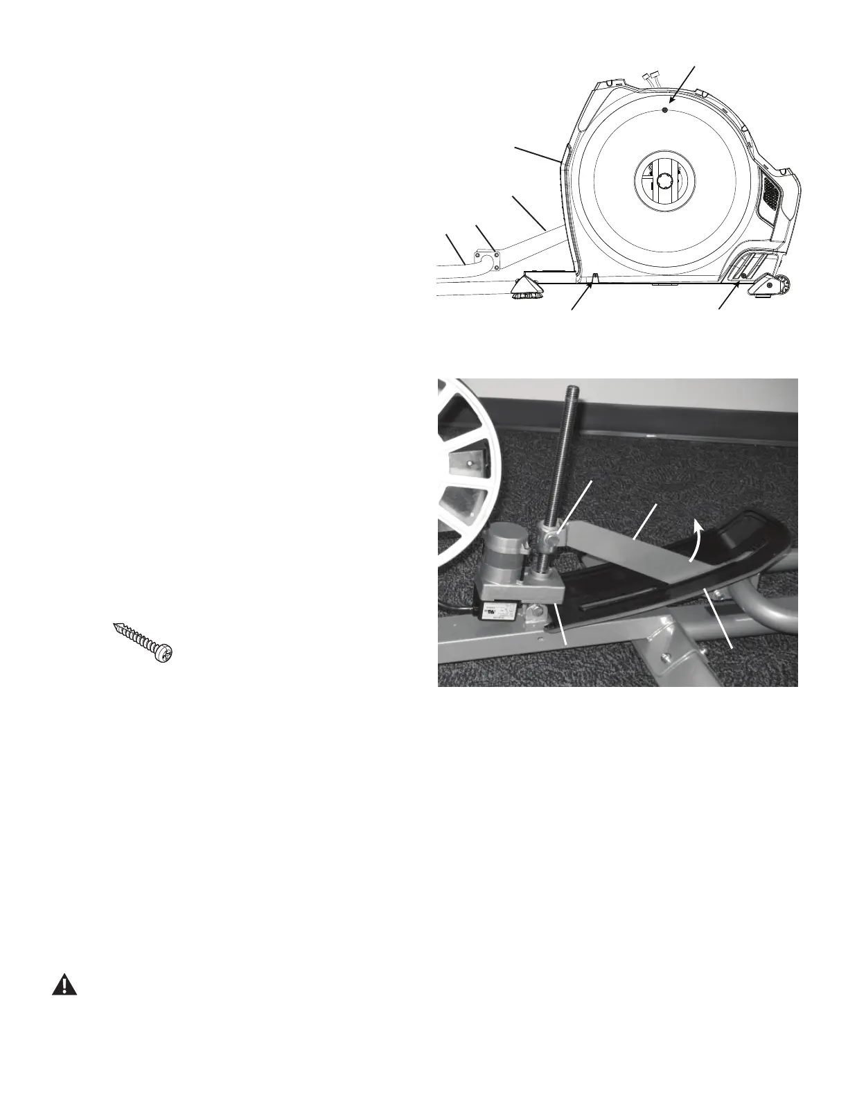
12. Using a #2 Phillips screwdriver, remove the 3 screws (*) that secure
WKH5LJKW6KURXG5HPRYHWKHERWWRPVFUHZV¿UVWDQGWKHQWKHWRS
screw. Slowly remove the Right Shroud.
If you are not replacing the Motorized Lift Cover—go to Step 15.
If you are replacing the Motorized Lift Cover (A)— loosen and
remove the hardware (C) that attaches the Incline Adjuster Assembly (B)
WRWKH5DLO$VVHPEO\'XVLQJWKHPPKH[NH\&RQWLQXHWR6WHS
13. Using the 18mm open end wrench, loosen the bolts (E) that attach
the Incline Adjuster bracket to the Lift Motor assembly (F) to allow the
Incline Adjuster (B) to pivot.
14. Tilt the end of the Incline Adjuster Assembly (B) up. Remove the
Motorized Lift Cover (A) from the Incline Adjuster Assembly.
15. Installation is the reverse procedure. Put the Left Shroud in postion
¿UVWWRDOLJQWKHVFUHZVIRUWKH5LJKW6KURXG,QVWDOOWKHWRSVFUHZV¿UVW
NOTICE: This step may require two people. Be sure not to crimp
any cables.
Note: Self-tapping screws attach the Shrouds to the Frame.
No screws hold the Lift Cover Shroud in position. Reach
through the left or right side opening to stabilize it while
installing the screws.
Be sure the tabs in the Top Shroud snap into the Main
Assembly.
Installation does not require the use of the crank puller. Be sure the Crank
Arms are connected at 180° from each other.
16. 'LVSRVHRIWKHROGSDUWV
17. Inspect your machine to ensure that all hardware is tight and
components are properly assembled.
Do not use until the machine has been fully assembled and
inspected for correct performance in accordance with the
Owner’s Manual.
Right side of main unit.
Left side of Lift Motor
A
B
E (X2)
F
A
B
C (X4)
D
*
(X3)

 Loading...