74
6. 'LVFRQQHFWWKHFDEOHVIURPWKH0RWRU&RQWURO%RDUGDIWHUQRWLQJWKHLU
locations.
Note: Be sure to note where all cables attach for re-assembly.
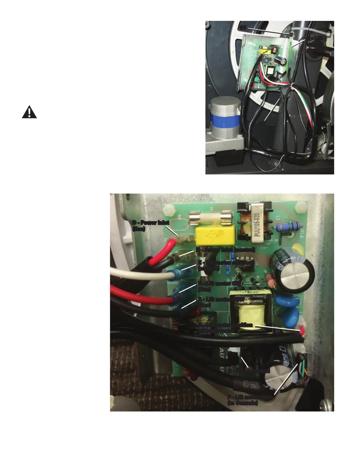
7. Using a #2 Phillips screwdriver, remove the 2 indicated screws (C1,
C2) that attach the MCB assembly to the Frame.
8. Remove old MCB assembly, and install the new MCB assembly.
Connect the cables to the MCB in their proper locations.
Use the top screw (C1) to attach the green Lift Motor ground
wire to the Frame. Be sure not to crimp any cables.
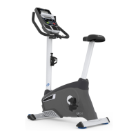
The MCB shown is on an E626 machine.
C2
C1
E - Lift
motor
ground
D - Power inlet
(line)
D - Power inlet (neutral)
E - Lift motor common
(neutral)
E - Lift motor CW
(line)
E - Lift motor CCW
(line)
E - Lift motor position
potentiometer
F - Lift motor wire
(to Console)
G - Servo control
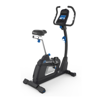
The MCB shown is on a Schwinn
™
470 machine.

 Loading...