165
18.Withtheassistanceofatleastasecondperson,iptheBase
Assembly until the Walking Belt rests on the ground.
Asthemachineisipped,theLiftingShockwillextendand
pivot the Base Frame and Incline Frame Weldments. Be sure
to be clear of any pinch opportunities and not to grasp the
Base Assembly from these shifting parts. Do not grasp the
Walking Belt since it can abruptly move.
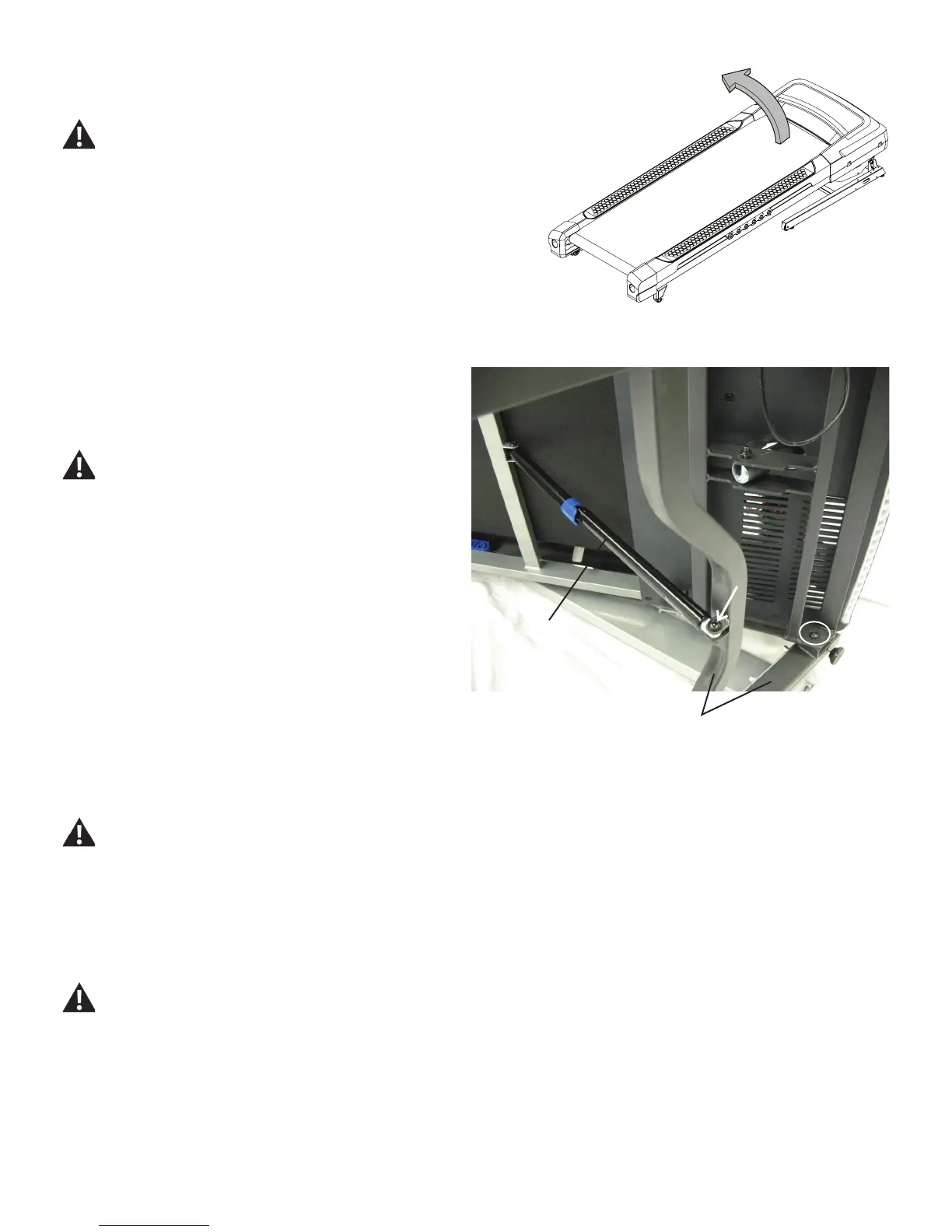
Note: the following image shows the Base Assembly on the side, not
fullyippedandrestingatontheWalkingBelt.
19. Using a 13mm wrench and a 6mm hex wrench, remove the indi-
cated hardware (with arrow) from the Lift Shock and lower the Base
Frame Weldment.
Be aware that when the Lift Shock is released from the Base
Frame Weldment, the Weldment may abruptly move and pivot
downward. Be sure to keep clear of any potential pinch
opportunities from this motion.
20. Using a 13mm wrench and a 6mm hex wrench, remove the 2
screws (one shown here with oval) from the Deck Frame and the
Base Frame Weldment.
21. Using a 13mm wrench and a 6mm hex wrench, attach the new
Base Frame Weldment to the Deck Frame.
22. Using a 13mm wrench and a 6mm hex wrench, re-attach the Lift
Shock to the Base Frame Weldment.
Be sure to keep clear of any potential pinch opportunities
when pivoting the Base Frame Weldment.
23.Withtheassistanceofatleastasecondperson,iptheBase
Assembly to the Upright position. Be aware that the Lifting Shock will
begin to compress when placed back to an upright position, lowering
the Base Assembly.
Be sure the area is clear around the Base Assembly before
ippingit.DonotgrasptheWalkingBeltsinceitcanabruptly
move.
Lift Shock
BaseFrameWeldment

 Loading...