19
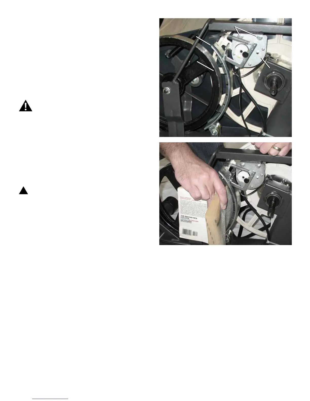
7. ToadjusttheBraketension,loosenthe2hexheadbolts
(C) and move the Servo Motor assembly (D) until the closest
pointontheBrakeMagnet(A)iswithin3.0mm(1/8”)ofthe
Flywheel (B). Tighten the bolts.
Note: If the cardboard is not 3mm (1/8”) thick, you can
use the pages of a paperback book to measure
thegap.Approximately36pages(sheets)=3mm.
8. Turn the power on again. Use the console to check the
resistance adjustment.
Machine is on. Current is active. There is risk of
electrical shock.
Note: Before fully attaching the Shrouds, remove the
cardboardfrombetweentheBrakeMagnet(A)and
the Flywheel (B). Power up the machine to verify
thattheMagnetArmcanmovefreely,andthatthe
Brake Magnet and Flywheel do not touch.
9. Final Inspection
Inspect your machine to ensure that all hardware is tight and
components are properly assembled.
!
Do not use until the machine has been fully
assembled and inspected for correct performance
in accordance with the Owner’s Manual.
B
D
A
C
 Loading...