Connector Panels Overview | 21
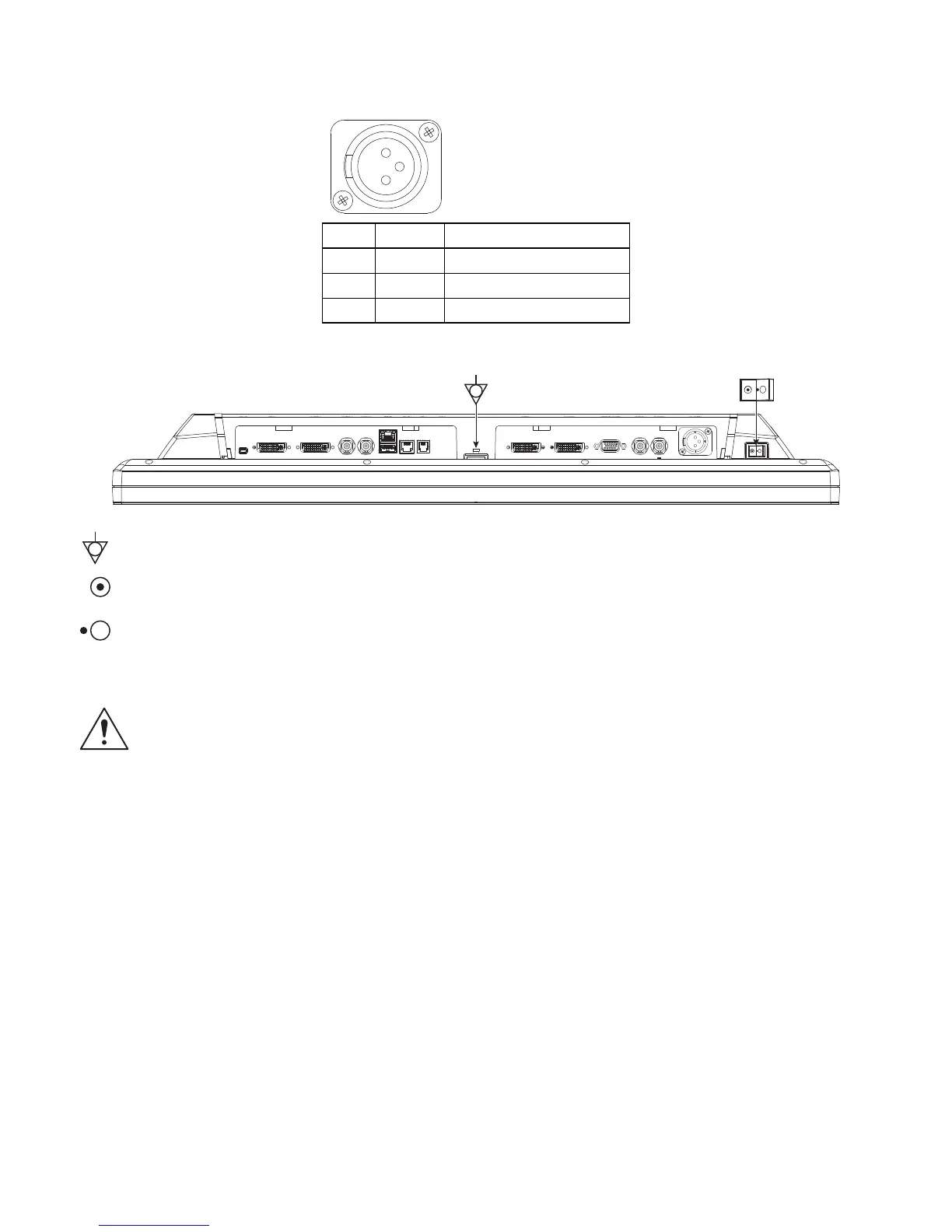
Power Connector and Pinout
24 VDC Connector
Electrical Symbols
Equipotentiality
This symbol appears next to the display Potential Equalization Conductor (ground post).
Closed (On) Switch
This symbol appears on the closed, or on, side of the display On/Off switch.
Open (Off) Switch
This symbol appears on the open, or off, side of the display On/Off switch.
Cable Bend Radius
We recommend that the bend radius of metallic cables be no less than 63 mm (2.5 inches) or 7 times
the diameter of the cable whichever is greater. The bend radius of Fiber Optic cables should be no less
than 10 times the diameter of the cable. Sharper bends can damage the cable, and/or degrade the
video signal.
Pin Name Description
1 GND Ground
2 GND Ground
3 +24 VDC Power Input
 Loading...