Installing PCBs
2-2 ◆ Section 2: PCB Installation DS2000 Hardware Manual
Installing PCBs
Central Processing Unit (CPU) PCB
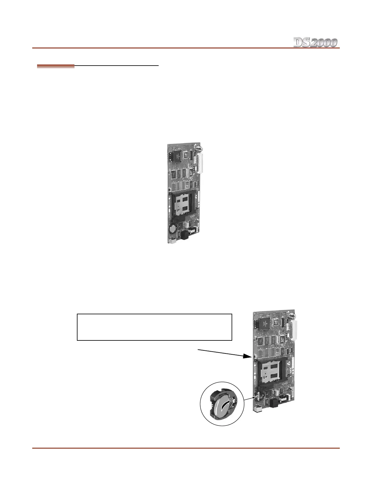
The CPU PCB (Figure 2-1) provides:
● The system’s central processing, stored program and memory for the customer’s site-specific data.
● PC Interface Card.
● Conference circuits, DTMF receivers and DTMF generators.
● External music input and on-board synthesized music source.
● External paging output and associated relay.
● Real Time Clock.
● Battery for short term (14 day) backup of the customer’s site-specific data.
Installing the CPU
The CPU PCB installs in the CN0 slot in the Main Equipment Cabinet.
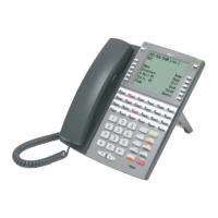
To install the CPU PCB (Figure 2-2) (Figure 2-3):
1. Slide the Mode Switch to the RUN position.
2. Insert the battery into the battery clips.
3. Plug the CPU into slot CN0.
Figure 2-1: CPU PCB
Figure 2-2: Setting Up the CPU
80
0
0
0 - 2
6
Refer to Section 4, Optional Equipment for instructions on
connecting the music source, External Paging, and the auxil-
iary relay.
Mode Switch
Battery