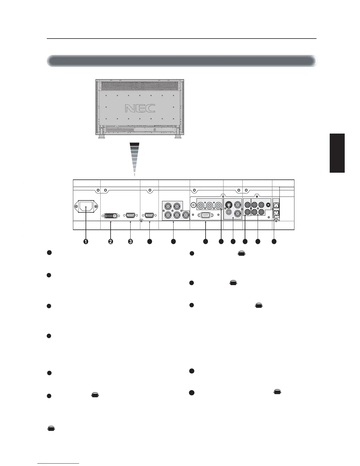
Terminal Panel
AUDIO IN 1,2,3
Input audio signal from external equipment such as a computer,
VCR or DVD player.
AUDIO OUT
Output the audio signal from the selected AUDIO IN source.
VIDEO INPUT/OUTPUT
VIDEO IN connector (BNC and RCA): Input a composite video
signal. BNC and RCA are not available at the same time.
(Use only one input).
VIDEO OUT connector (BNC): Output the composite video
signal from the VIDEO IN source.
S-VIDEO IN connector (DIN 4 pin): Input the S-video (Y/C
separate signal). See page 26, S-VIDEO MODE SETTING.
EXTERNAL CONTROL (mini D-Sub 9 pin) RS-232C
Input signal from control equipment such as a computer.
EXTERNAL SPEAKER TERMINAL
Outputs the audio signal from the selected audio source.
AC IN connector
Connects with the supplied power cord.
RGB 1 IN (DVI-D)
To input digital RGB signals from a computer.
* This connector does not support analog input.
RGB 2 IN (mini D-Sub 15 pin)
To input analog RGB signals from a personal computer or other
RGB equipment.
RGB 3 IN [R, G, B, H, V] (BNC)
To input the analog RGB signals from a computer or other RGB
equipment. A Sync-on-Green signal can be connected to the G
connector.
RGB OUT (mini D-sub 15 pin)
To output the signal from the RGB 2 or 3 IN connector.
DVD/HD (BNC)
Connecting equipment such as a DVD player, HDTV device, or
Laser disc player.
Parts Name and Functions -continued