A
B
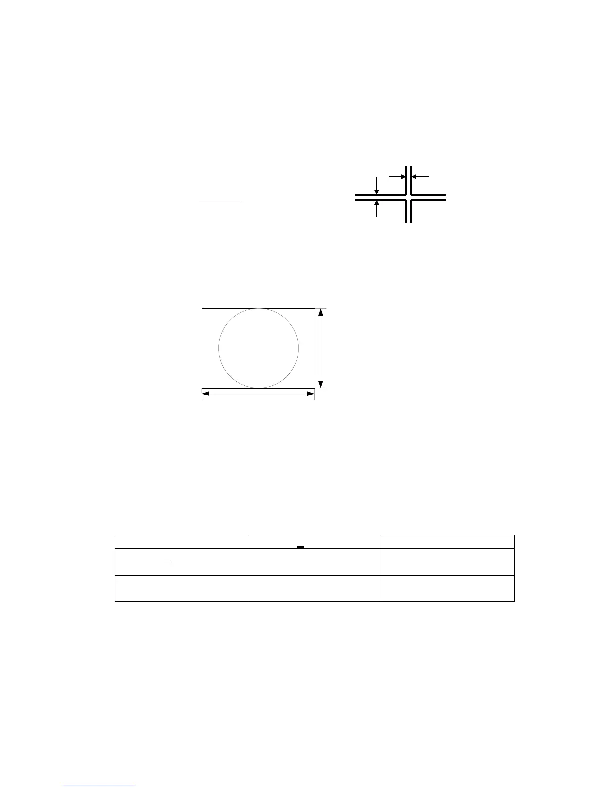
270mm
203mm
A Zone (A circle 203 mm in the center of the CRT face center)
C
H
, C
V
: Within 0.35 mm
C
S
: No rule
B Zone (Areas outside of zone A within the rectangle of 270 mm×203 mm)
Safety with the list below.
C
H
< 0.35 mm 0.35 mm < C
H
< 0.40 mm
C
V
< 0.35 mm OK Calculate C
S
and judge
Within 0.50 mm
→
OK
0.35 mm < C
V
< 0.40 mm Calculate C
S
and judge
Within 0.50 mm
→
OK
Need to touch up
27
7. Purity
(1) Receive signal 14(Cross hatch pattern).
(2) The CRT face should be facing east and degauss the entire unit by external degaussing coil.
(3) Make sure the single color purity.
If not, readjust CPC magnet and touch up using correction magnets.
8. Convergence
C
H
: Convergence error of horizontal direction
C
V
: Convergence error of vertical direction
C
S
: Total direction of Convergence error
(Calculate by “√C
H
² + C
V
² ”
(1) Receive signal 14(Cross hatch pattern).
(2) Measure convergence error., If it is out of spec, adjust static convergence by 4-pole magnets and
6-pole magnets.
C
H
C
V