5. Vertical compensation and geometrical compensation of the raster
LM1295:
1. Vertical scanning frequency : 50 to 100Hz.
2. DC control compensation amplitude
3. Temperature stability of the vertical amplitude : 1%.
4. Dynamic vertical deflection compensation corresponding to the secondary anode voltage drop.
5. Positive and negative compensation signals.
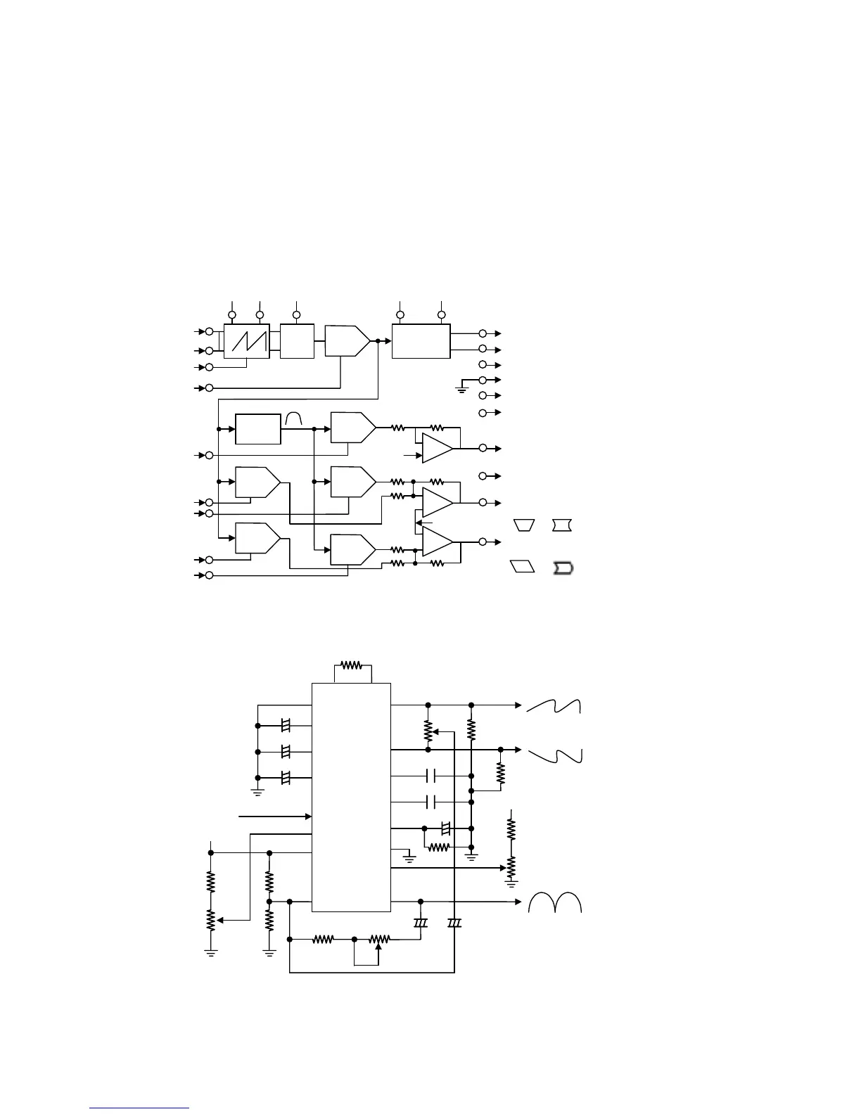
Block Diagram
LM1295 Application
VR4
R1 10K
Ω
U1
LM1295
21
22
1
3
5
8
4
2
7
616
15
17
18
20
19
23
24
C1
C2
C3
10uF
100uF
10uF
Negative
going V Sync
12V
R2
10K
Ω
VR1
5K
Ω
R3
150K
Ω
R4
50K
Ω
R5
10K
Ω
VR2
200K
Ω
S Amplitude Adj.
C4
10uF
C5
10uF
VR3
5K
Ω
R7
10K
Ω
300K
Ω
R6
C6
4.7uF
C7
0.47uF
0.1uF
C8
R8
10K
Ω
R9
10K
Ω
200K
Ω
S Center Adj.
TO V Deflection
Output Amp.
Rvert
Rvert
Gnd V Drive
4V Cap
8V Cap
V Drive
Vref Cap
OSD Cap
21 Cap
V Sync in
ALC Cap
V Height
Gnd
Vcc
V Dyn
Height
V Dyn
Focus
V Dyn
Focus Cntl
V Sync in
Osc.
V Height
Auto
Level
Gain
Ad