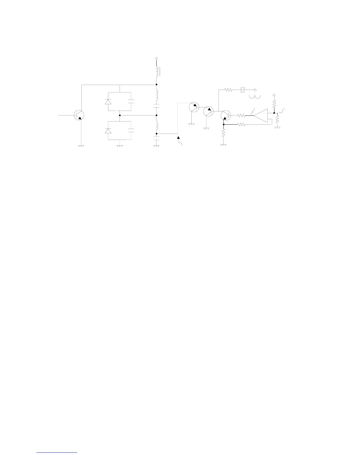
8. Horizontal amplitude control
Circuit Diagram
Description of the circuit:
1) The diodes D1 and D2 compose the bipolar modulation circuit, and have the function of controlling
the currents of the oils DY(lpp) and Lm(lm) through voltage modulation carried out by utilizing VM.
B+ = Vm +Vcs Therefore, Vcs = (ly * Ly)/ts → ly = (Vcs * ts)/Ly, with B+ fixed.
Such being the case, the horizontal width decreases when Vm ↑ → Vc ↓ → ly ↓
Inversely, the horizontal width decreases when Vm ↓ → Vcs ↑ → ly ↑
(B+ = (Vp*2Tr)/(π*Ts), Tr =
¡Ô¡Ô
¡Ô¡Ô
¡ÔLyCt, Tm =
¡Ô¡Ô
¡Ô¡Ô
¡ÔLmCm)
2) Q2, Q3, Q4 and U1 compose the control circuit of H-WIDTH. Of those devices, the transistor Q1 and
Q2 compose the Darlington current amplifier, and on the other hand the transistor Q4 and the opera-
tional amplifier U1 compose the emitter-coupled circuit, that stabilize the voltage and control the
current.
3) The horizontal width broadens when Va ↑ → VbI ↑ → I1 ↑ → I2 ↑ → Vm ↓ →. An inference in
the opposite sense is also possible.
Test points for maintenance:
1) C
T
= 31 to 37 kHz = 3.2 us
48 to 64 kHz = 3.0 us
Cm ÷ 2.8 us
2) V
A
CENTER: 31 to 64 kHz
¡Ü¡Ü
¡Ü¡Ü
¡Ü 1.91 to 4.06V
V
M
CENTER: 31 to 64 kHz
¡Ü¡Ü
¡Ü¡Ü
¡Ü 11.6 to 27.4V
R2
D2
R1
Q2
R3
CT
D1
CS
B+
C1
Q1
Q3
Q4
R4
R5
R6
U1
Cm
Csm
Lm
DY
V
B
V
A
DC
H-Width
AC PIN
Vm
64