EasyManuals Logo

NEC SL1100 Hardware Guide

NEC SL1100
164 pages
To Next Page IconTo Next Page
To Previous Page IconTo Previous Page
Page #80 background imageLoading...
Page #80 background image
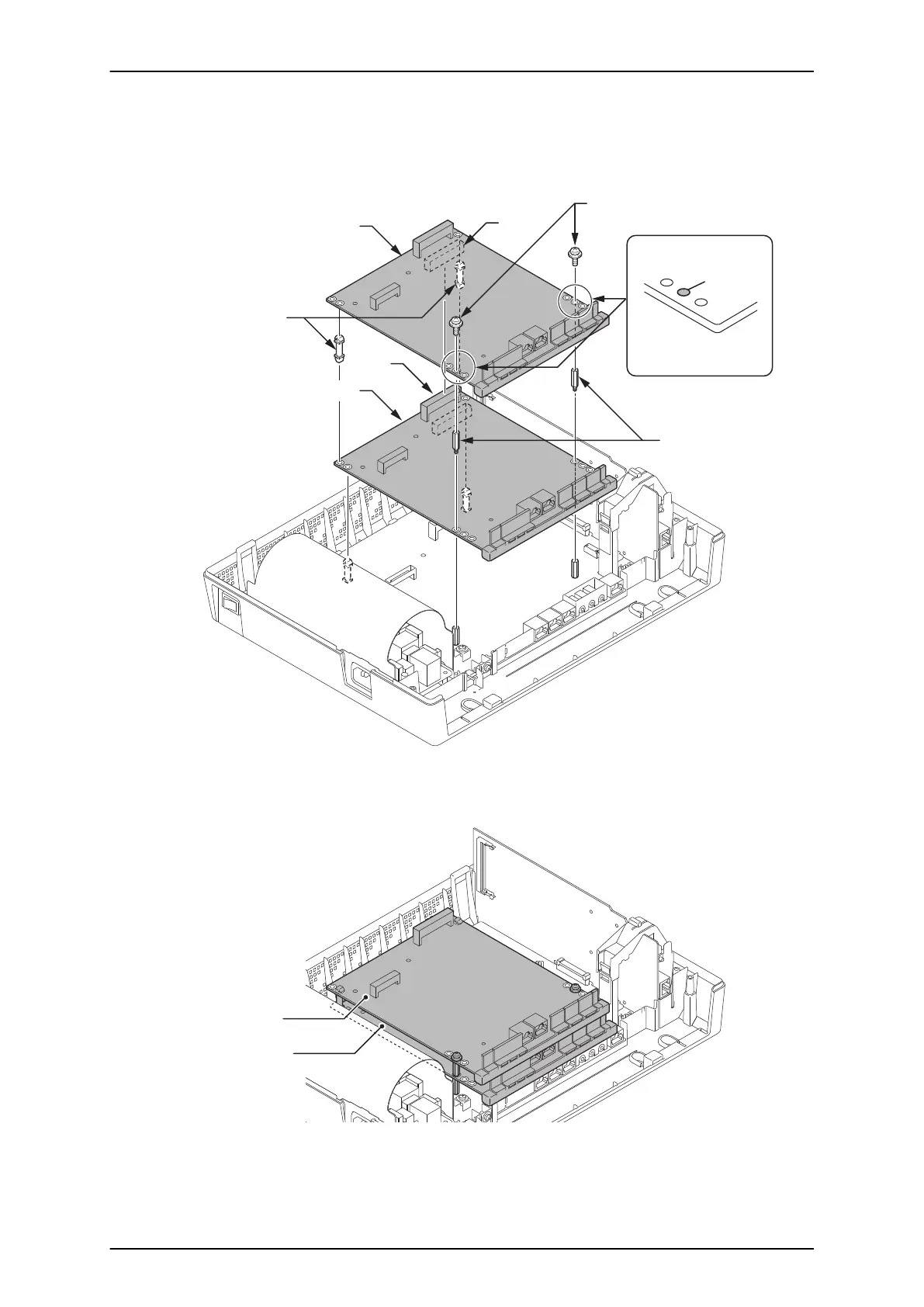
5. In case a 2nd PCB is mounted, insert two Nylon-spacers into the specified holes, and fasten two
Metal-spacers into the specified holes. (Both Nylon and Metal spacers are provided with 080E/
008E/000E/1PRIU)
Fasten two screws to secure the 2nd PCB to the top of the 080E/008E/000E/1PRIU.
Expansion Interface Card
(2nd PCB)
J1
J2
Nylon-Spacers
Metal-Spacers
Screws
Expansion Interface Card
(1st PCB)
Screw position
Both sides are
the same.
2nd EXP.
PCB
Figure 2-65 Mounting the 2nd Expansion Interface Card
6. Following illustration shows an example for installing two expansion PCBs onto the KSU.
2nd PCB
1st PCB
Figure 2-66 Mounting Two Expansion Interface Cards
SL1100
ISSUE 6.0
2-46 Installation

Table of Contents

Other manuals for NEC SL1100

Questions and Answers:

Question and Answer IconNeed help?

Do you have a question about the NEC SL1100 and is the answer not in the manual?

NEC SL1100 Specifications

General IconGeneral
System TypeHybrid
VoIP CapabilityYes
Integrated VoicemailYes
Auto AttendantYes
Conference CallingYes
Caller IDYes
Music on HoldYes
Power Supply100-240 VAC, 50/60 Hz
Humidity10% to 90% (non-condensing)
TypeBusiness Phone System
Maximum VoIP Channels16
Operating Temperature0°C to 40°C

Related product manuals