© by NECTA VENDING SOLUTIONS SpA
6
0301 162-00
CONNECTING THE MACHINE TO
THE POWER SUPPLY
The machine is designed to operate under a single-phase
voltage - 120 V~ 60 Hz - and is protected by 15 A fuses.
Before making the connection make sure that the ratings
correspond to those of the power grid, and more specifi-
cally:
- the supply voltage rating should be within the limits
recommended for the connection points;
- the main switch should be capable of withstanding the
peak load required, and at the same time ensure proper
omnipolar disconnection from the power grid with an
opening gap of the contacts of at least 3 mm.
The main switch, the power outlet and the plug should
be located within easy reach.
The electrical safety of the machine is ensured only when
it is correctly and efficiently earthed according to the safety
standards in force.
This fundamental safety requirement must be duly
verified, and if in doubt the system must be carefully
tested by qualified technicians.
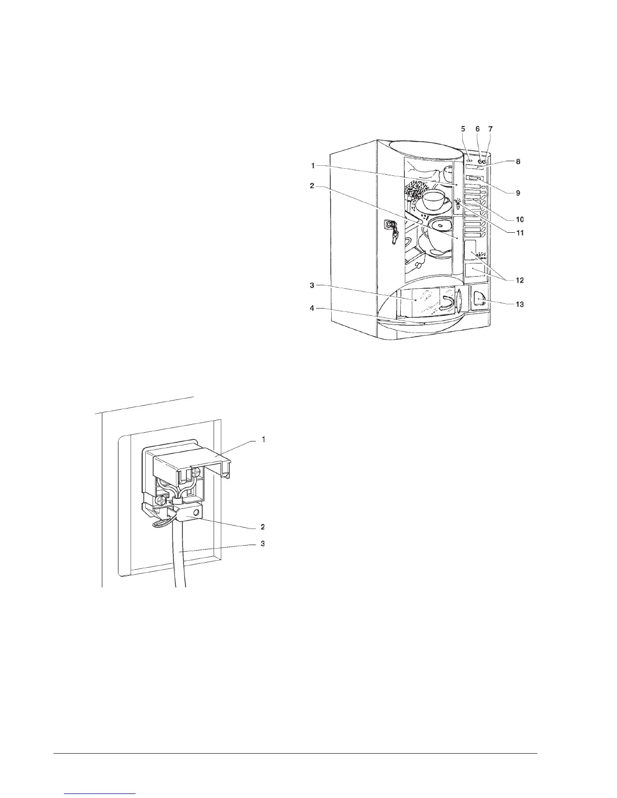
The power cable is of the type fitted with a fixed plug.
Any replacement (see Fig. 5) should be done by qualified
personnel only, using exclusively cables of the type UL
SJT 3x16 AWG.
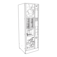
CONTROLS AND INFORMATION
All user controls and information are located on the exter-
nal side of the door (see Fig. 6).
The labels with the selection menu and the instructions
supplied with the machine must be inserted at the time of
installation, referring to the selection dose table.
Fig. 5
1 - Lift cover
2 - Cable clamp
3 - Cable from grid
Do not use adapters, multiple sockets and/or exten-
sions.
THE MANUFACTURER DECLINES ALL RESPONSI-
BILITY FOR ANY DAMAGE CAUSED BY NONCOMPLI-
ANCE WITH THE ABOVE MENTIONED SAFETY RULES.
Fig. 6
1 - Prearrangement for payment systems
2 - Spaces for product labels
3 - Dispensing compartment
4 - Liquid waste tray
5 - Coin slot
6 - "Exact amount" warning light
7 - Coin return button
8 - Instruction labels
9 - Alphanumeric display
10 - Available selection menu
11 - Jug facilities / free vend key
12 - Prearrangement for front validator and/or labels
13 - Coin return compartment
The Programming button, used to access the machine
functions, is located on the internal side of the push-button
board.
Press the Programming button twice to access the "Pro-
gramming" mode.
Press selection button No. 5 to automatically start filling the
machine water system.
DOOR SWITCH
When opening the door a special switch disconnects the
power from the machine electrical system,
except from the terminal board supporting the line
cable and from the fuse box. Before removing the
cover from these parts (marked by a special plate) it is
necessary to disconnect the external switch.
To energize the system with the door open, simply insert
the special key into the slot (see Fig. 7).