© by N&W GLOBAL VENDING S.p.A. 13 10 2009 3325 - 00
LABELS INSERTION
To insert the selection labels, disassemble the plate sup-
ports after having removed the three fastening screws by
acting on xing clips (see g. 17).
Insert the plates into the slots alternatively opening on
the right and left side.
Some buttons may not be used according to the models
(see the selection dose table).
The self-adhesive plates also supplied shall be applied
to the product containers according to the arrangement
(see the selection dose table).
WATER SYSTEM CONNECTION
The vending machine must be connected with the drink-
able water system according to the provisions in force in
the place of installation of the equipment.
The mains pressure must range from 0.05 to 0.85 Mpa
(0.5 8.5 bar).
Let water come out of the water network until it is limpid
and free of any trace of dirt.
Connect the water network with the 3/4” gas union of the
water inlet solenoid valve by means of a tube that can
support the network pressure and of a type suitable for
foodstus (min. inner diameter 6 mm.) (see g. 18).
It is recommended to apply a cock on the water net-
work outside the machine in an accessible position.
anTiflood device
The water inlet solenoid valve (see g. 18) is complete
with an antiood device that can mechanically lock the
water inlet as a result of a malfunction of the solenoid
valve or the water level control gear in the boiler.
To restore the normal operation, act as follows:
- power off the machine;
- discharge water in the overflow tube;
- close the water network cock outside the machine;
- loosen the union intended to fasten the supply tube of
the solenoid valve to discharge the residual network
pressure and tighten it again;
- open the cock and power on the machine (see fig. 18).
decalcifier
The machine is supplied without a decalcier.
If water is very hard, you can mount a decalcier.
Decalciers, available as an accessory, shall be regener-
ated according to the manufacturer’s instructions at regular
intervals
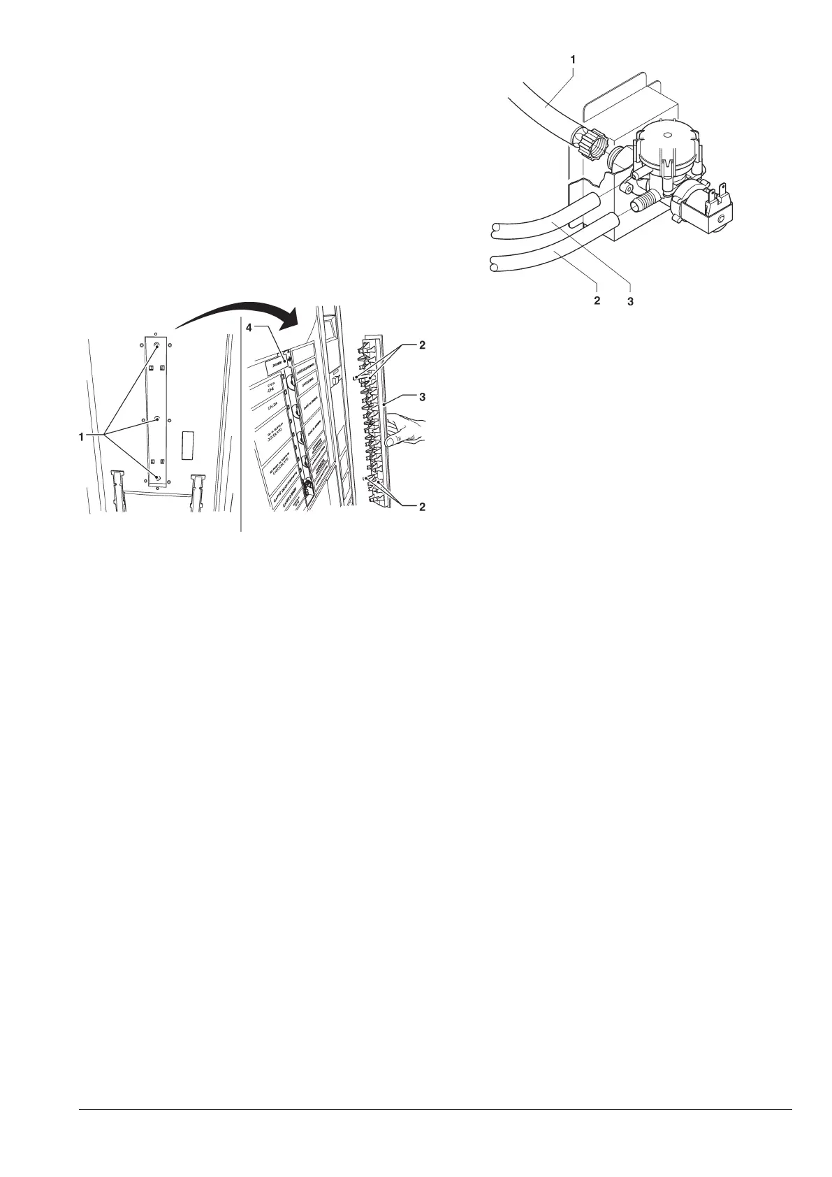
Fig. 17
1- Fastening screws
2- Fixing clips
3- Plate support
4- Selection labels
Fig. 18
1- ¾” gas water inlet union
2- Inlet tube union
3- Overflow tube