© by N&W GLOBAL VENDING S.p.A. 12 10 2009 3325 - 00
Chapter 2
Installation
Installation and any subsequent maintenance opera-
tion must be carried out when the machine is live and,
therefore, by the personnel skilled and trained on the
use of the machine as well as aware of the specic risks
such a condition may involve.
The machine must be installed in a dry room, at a tem-
perature between 2° and 32°C and it can not be installed
in a room where water jets are used for cleaning (e.g.
large kitchens, etc.).
At the time of the installation, it is necessary to
completely sanitise the water circuits and the parts
in contact with foodstus in order to remove any
bacterium that may have built up during storage.
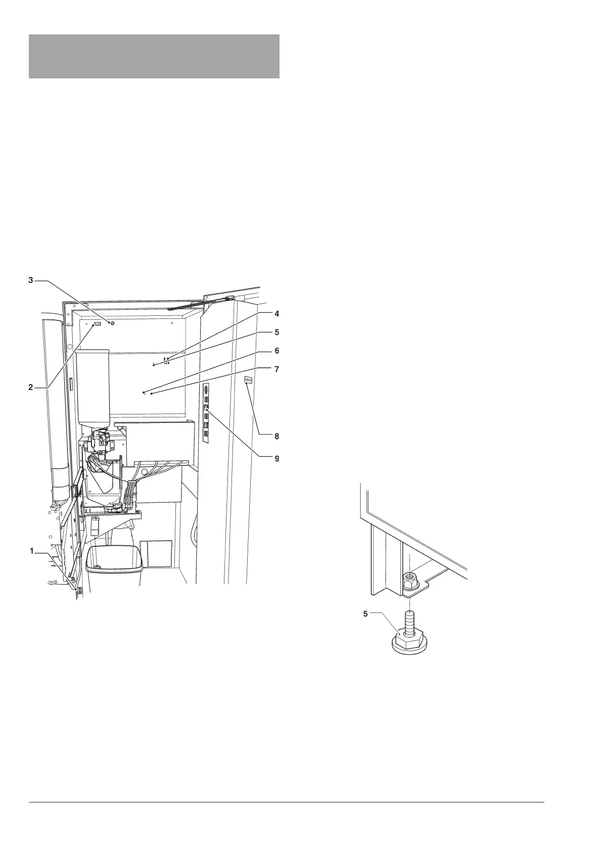
door swiTch
Whenever you open the door, a special switch will power
o the electric installation of the equipment.
To power on the machine when the door is open, just
insert the key into the slot (see g. 15).
When the door is open, you are not allowed to
access any live part. Only the parts protected by
covers and marked by the plate “power o before
removing the cover” will remain live inside the
machine.
Before removing these covers, it is necessary to
detach the power supply cable from the mains.
You can close the door only after having removed the
key from the door switch.
UNPACKING THE VENDING MACHINE
After having unpacked the machine, make sure that the
equipment is intact.
In case of doubt never use the equipment.
No packing material (plastic bags, foam polysty-
rene, nails, etc.) should be left within the reach of
children since they are potential sources of danger.
Packing materials shall be disposed of in authorised
dump sites and recyclable ones collected by specialised
companies.
Important!!
The machine shall be arranged to prevent maximum
inclination from exceeding 2°.
If necessary, level it by using the adjustable feet (see g.
16) supplied with the machine.
Fig. 15
1- Door switch
2- Permanently live socket (230V~ 2 A max)
3- Mains fuse
4- Card leds
5- Mechanical counter
6- Open door signalling switch
7- Service buttons
Fig. 16
1- Adjustable foot